Due to the fast response speed, the photoelectric sensor can realize non-contact measurement, and has high precision, high resolution and good reliability. In addition, the photoelectric sensor has the advantages of small size, light weight, low power consumption and easy integration, and is currently the most productive and applicable. One of the widest sensors is widely used in military, aerospace, communications, smart home, intelligent transportation, security, LED lighting, toys, inspection and industrial automation control.
Smoke turbidity monitoring of photoelectric sensorsPreventing industrial soot pollution is one of the important tasks of environmental protection. In order to eliminate industrial soot pollution, we must first know the amount of soot emissions, so we must monitor, automatically display and exceed the standard alarm. The turbidity of the soot in the flue is detected by the magnitude of the change in the transmission of light through the flue. If the turbidity of the flue increases, the light emitted by the light source is increased by the absorption and refraction of the soot particles, and the light reaching the photodetector is reduced, so that the intensity of the output signal of the photodetector can reflect the change in the turbidity of the flue.
The smoke alarm also uses a photoelectric sensor as the core component, which can be used to measure the concentration of smoke. It consists of an infrared light-emitting diode and a phototransistor, but the two are not on the same plane (having a certain angle). In the smokeless state, the phototransistor does not receive infrared light; when the smoke enters the sensing chamber, the smoke particles will scatter some of the light beam onto the phototransistor. When the concentration of smoke gradually increases, more beams are received. Scattered onto the sensor, the buzzer will give an alarm when the beam reaching the sensor reaches a certain level.
Photoelectric sensor in barcode scanning pen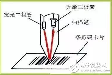
When the scanning tip moves on the barcode, if the black line is encountered, the light of the LED will be absorbed by the black line, and the phototransistor will not receive the reflected light, which is high impedance and is in the off state. When a white space is encountered, the light emitted by the LED is reflected to the base of the phototransistor, and the phototransistor generates a photocurrent to conduct. After the entire barcode is scanned, the phototransistor deforms the barcode into an electrical pulse signal. After the signal is amplified and shaped, the pulse train is formed, and then processed by the computer to complete the identification of the barcode information.
Photoelectric sensor counts in the money counterOne of the essential components of the money counter is the photoelectric sensor. The counter of the money counter uses non-contact infrared photoelectric detection technology, which has the advantages of simple structure, high precision and fast response.

The counter of the money counter uses two sets of infrared photoelectric sensors. Each sensor consists of an infrared light-emitting diode and a phototransistor that receives infrared light with an appropriate distance between them.
When no banknotes pass, the receiving tube is illuminated by light and the output is zero. When there is a banknote passing through the moment, blocking the infrared light, the luminous flux of the receiving tube is insufficient, and the output is 1. After the banknote passes, the receiving tube receives infrared light to conduct. In this way, a pulse signal is generated at the output end of the circuit, and these signals are input and amplified by the subsequent circuit shaping, and the single-chip microcomputer drives the motor, and the counting and display are completed accordingly. The reason why the money counter uses two sets of photoelectric sensors is to detect the integrity of the banknotes and avoid the credits being counted.
The photoelectric sensor is used to detect the counting of the banknotes to realize the accumulation of the number of banknotes. Finally, the number of banknotes is visually displayed to the user by the liquid crystal and the external display portion, and the user can be automatically alerted when an abnormality occurs.
Photoelectric sensor applied to automatic meter reading systemWith the development of microelectronics, sensor technology, computer technology and modern communication technology, photoelectric sensors can be used to develop automatic meter reading systems. The aluminum disk of the electric energy meter is driven to rotate by the torque generated by the eddy current and the magnetic field. The photoelectric sensor can convert the number of revolutions of the aluminum disk into a pulse number. For example, if the rotating bright aluminum plate is partially blackened, and then the reflective photoelectric emission receiving tube is used, when the aluminum disk rotates, a pulse is generated at the local blackening, and the number of revolutions of the aluminum disk can be sampled. Converted to the corresponding number of pulses, and sent to the T0 port of the CPU for counting processing via the optocoupler isolation circuit. The use of optocoupler isolators can effectively prevent interference signals from entering the microcomputer. Combined with other transmission methods, an automatic meter reading system can be formed.
Photoelectric sensors are applied in automated production linesPhotoelectric detection method has the advantages of high precision, fast response, non-contact, etc., and is widely used in light industrial automata.
Photoelectric strip deviation detectorThe strip deviation detector is used to detect the size and direction of the strip material in the correct position during processing, thereby providing a correction signal for the rectification control circuit, which is mainly used in the production process of printing, dyeing, paper feeding, film and tape.
The principle of photoelectric strip deviation detector is shown in Figure 1. The light from the source converges through the lens 1 into a parallel beam that is directed toward the lens 2 and then concentrated onto the photoresistor. On the way that the parallel beam reaches the lens 2, part of the light is blocked by the strip under test, reducing the amount of light transmitted to the photoresistor.
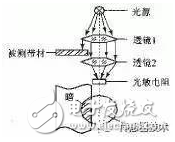
Figure 1 Working principle of strip deviation detector
Figure 2 is a simplified diagram of the measurement circuit. R1 and R2 are the same type of photoresistors. R1 is mounted as a measuring component under the strip, and R2 is covered with a hood to provide temperature compensation. When the strip is in the correct position (middle position), the bridge consisting of R1, R2, R3, and R4 is balanced to make the amplifier output voltage U0 zero. When the strip is left-biased, the shading area is reduced, the resistance of the photoresistor R1 is reduced, and the bridge is out of balance. The differential amplifier amplifies this unbalanced voltage and the output voltage is negative, which reflects the direction and magnitude of the strip's deviation. Conversely, when the strip is right-biased, U0 is a positive value. The output signal U0 is displayed on the one hand by the display and on the other hand is sent to the actuator to provide a correction signal for the correction control system.
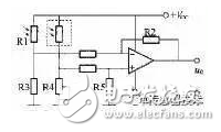
Figure 2 Strip deviation detector measurement circuit
Packing filling height detectionThe volumetric method is used to measure the finished product of the package. In addition to the certain error range of the weight, there are certain requirements for the filling height to ensure the appearance quality of the product. The finished product that does not meet the filling height will not be allowed to leave the factory. Figure 3 shows the principle of controlling the filling height by means of photodetection technology. When the filling height h deviation is too large, the photoelectric connector has no electrical signal, that is, the packaged article is pushed out by the actuator for processing.
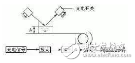
Figure 3 Using photoelectric detection technology to control the filling height
80mm embedded thermal printer, super large paper warehouse design, widely used in large self-service terminal equipment such as medical treatment and factories, simple appearance design, support various system development. It does not need carbon ink, adopts thermal printing technology, and only needs thermal paper roll to print all kinds of content. It is an economical and fast printing. Embedded Printer supports the secondary development of major systems. There are two types of manual tearing and automatic cutting.
80Mm Embedded Bill Printer,80Mm Panel Printer,Large Paper Storage Embedded Thermal Printer,Easy To Install Printer
Shenzhen Geyi Technology Co., Ltd. , https://www.gy-printer.cn