Abstract: Combining with the production status of China's automobile industry, a method for computer automatic identification of automobile wiring harness drawings is studied and discussed. The method is tested by computer software. Under the condition of a certain pre-set drawing rule, the wire harness in the drawing is judged according to the programmed program, and the required wire harness and wire harness segment are selected and merged according to the class. Finally, the purpose of automatically completing the harness length and harness classification identification is achieved. This new identification method has been greatly innovated compared with the traditional manual reading, segmentation calculation, and summation method, which greatly improved the production efficiency of China's automobile industry and reduced the error rate of personnel operation. Enterprise production brings direct benefits.
Key words: computer simulation; automotive wiring harness drawing; harness; automatic identification
This article refers to the address: http://
0 Introduction Automotive wiring harness is known as the car nerve, is the carrier to control the car's electrical signal, is an important part of the car circuit, there is no car circuit without the wire harness. Automobile wiring harnesses are composed of wires, connectors, fasteners, rubber parts, and insulated and shielded tubes. It organically connects the central control unit with the vehicle control unit, electrical and electronic actuators, electrical and lighting displays to form a complete automotive electrical control system. Correct and fast identification of automotive wiring harnesses is very important for the entire automotive circuit.
At this stage, the wire harness technology of China's auto industry still uses traditional technology. The traditional cable blanking is to classify the length of various line types by manual reading, segmentation calculation, and summation. Various components The number of data, etc., so as to be used as an account voucher when purchasing the line material. This traditional measurement method can be used for simple drawings, but with the vigorous development of China's automobile industry, the design of automobile structure is becoming more and more complicated, and the number of wiring harnesses and supporting electrical connectors as the central nervous system of automobiles has doubled. At present, the total length of the wire harness used in a car has reached more than 4,000 meters. The internal structure of the new power car is more complicated than the internal structure of the traditional fuel-powered car. Obviously, in this case, the traditional wire harness cable metering method can not adapt to the current working mode, and has the disadvantages of low efficiency, many errors, and large workload. Therefore, in the face of more complex wiring harness design requirements, ensuring the correctness of design results and improving efficiency is the key to meeting the requirements of new power vehicles for wiring harnesses. Here you can learn from these tasks and effectively identify the automotive wiring harness drawings.
1 Introduction to automobile wiring harness drawing The wiring harness drawing of the automobile is composed of automobile wiring harness and automobile components. It is a two-dimensional drawing drawn by drawing software such as AutoCAD and opening CAD. The drawing depicts the length, direction, connection mode, and classification of the wiring harness of the wire harness. Properties such as material and wire diameter, component type, and specifications. Figure 1 is a simpler wire harness drawing. Take Figure 1 as an example to show how to use a computer to automatically identify a car harness drawing.

It should be noted that since the wire harness drawing is only a schematic diagram of the actual wire harness, the straight line length of the wire segment is not the same as the actual physical length represented by the wire segment. The length of the text box label is the actual length of the segment. By analyzing the harness drawing, the harness is a simple diagram of the connection composed of multiple segments.
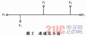
Figure 2 shows a simple connection diagram of Figure 1. In Fig. 2, V1, V2, V3, V4, and V5 indicate the vertices of the respective beam segments, respectively.
2 Automatic identification of the wire harness Because the wire harness is mainly composed of wire segments. Therefore, through the design process, the computer automatically determines the coordinates of the starting point and the end point of the segment after reading the drawing according to the established rules, analyzes the connection relationship between the segments, reads the length of the segment, and finally calculates the length of the same harness. To achieve automatic recognition of drawings.
For the representation characteristics of the wire harness, the automatic identification rule of the wire harness is established, and the automatic identification of the wire harness segment and the wire harness is the key point for automatic identification of the wire harness.
2.1 Function Module Diagram The design of the automatic identification function module is shown in Figure 3.
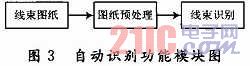
It can be seen from the function module diagram that before the wire harness drawing is recognized, the drawing pretreatment is first performed, and then the wire harness identification is performed. Among them, harness identification is realized by computer software. Because the computer is mainly object-oriented to identify the drawings. Therefore, for a drawing, once the wire harness is obtained in the program, the line width, length, color and other properties of the wire harness are obtained. Thereby, the wire harness can be judged according to these attributes of the wire harness to realize wire harness identification.
2.2 Flowchart The flow chart for automatic identification of harness drawings is shown in Figure 4.
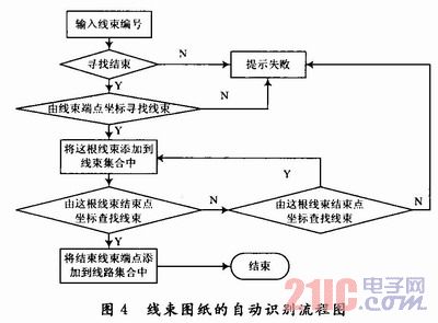
In the flow chart, finding the wire harness and finding the wire harness according to the coordinates of the end point of the wire harness are two concepts. Through the program, the wire harness that the former finds is the wire harness on the entire wire harness drawing, including the required and unnecessary, and this step is to find the coordinates of the end point. The wire harness was paved. Finding the harness by endpoint coordinates is based on the previous step, ignoring the unwanted harness and finding the harness to identify, adding the harness to the line set.
2.3 Drawing identification specific work It can be seen from the automatic identification function module diagram and flow chart that the identification of harness drawings is mainly divided into the following seven parts:
(1) Prepare the wiring harness drawing identification rules;
(2) pre-processing the drawings;
(3) reading the two-dimensional wire harness drawing (CAD vector drawing) primitive;
(4) Find a line set according to the coordinates of the end point of the harness;
(5) Determine the end point of the harness and determine the set of unique harness routes;
(6) The length of the harness is read one by one by the harness concentrated by the harness;
(7) Add the harness lengths and output the result.
2.3.1 Harness Drawing Recognition Rules Because there are many uncertainties in the drawing process of the wire harness drawing, including the thickness of the wire harness, the position, the position of the text, etc., according to the nature of the wire segment and the wire harness, a certain identification rule is established, so that It is very important to improve the accuracy and recognition efficiency of drawing recognition. Drawing recognition rules are applied to computer programs that the computer can use to determine drawings. Because the wire harness drawing is a third-party drawing, the key is to use the rules to digitize the elements in the drawing and the drawing to facilitate the judgment of the computer. For example, open a CAD drawing, the computer "sees" a line, the program can get this line called line1 according to the properties of the line, the length is * *, the color is * *, etc., which is digitized. Below, an automatic identification rule indicating the segment and text annotation is given:
Rule 1: To indicate the start and end of the segment, place the segment in the middle of the two black dots. Therefore, black dots and lines are used as markers for judging the segment of the line;
Rule 2: Text labeling should be expressed as (length of the segment, segment attribute), such as 274 or 274VT or 274 flower bag;
Rule 3: The text labeling should be in the identification area where the line segment is a symmetry line and the symmetry distance is d, wherein the parameter d can be dynamically adjusted when the drawing is recognized;
Rule 4: If there is more than one text in the recognition area, select the smallest angle with the line segment, or use the method of area coverage to identify;
Rule 5: If there are multiple text labels in the recognition area, according to the principle of the center, select the text label of the nearest point of the offline beam segment or adopt the method of area coverage.
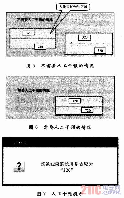
Area coverage method: For the cases mentioned in rules 4 and 5, increase the line width by 2 times the "line length text box" to get a rectangular area. If the "harness length text box" falls in this area, it means this. The length of the harness. If more than 2 "harness length text boxes" are found and the lengths indicated by these "harness length text boxes" are different, manual intervention is required. As shown in Figure 5 to Figure 7.
2.3.2 Drawing Preprocessing Because the normative requirements of the drawings are inconsistent, the drawing habits of the designers are different, so there are many uncertain factors in the drawing process, such as the connection break between straight lines in the drawing, the straight line connecting the head, the straight line by The composition of multiple coincident straight segments, etc., these uncertain factors will have a significant impact on the analysis and identification of the drawings. Therefore, it is necessary to manually pre-treat the harness drawings before the drawing is recognized. The final purpose of the pre-processing is to hope that the harness drawings meet the requirements of the rules.
2.3.3 Reading 2D Harness Drawings Open a 2D drawing and use the program to identify all the lines in the harness drawing. Some of these lines are required segments, and some are unwanted. At this time, it is necessary to judge and extract the required line by the rule to identify. For example, for Figure 1, the required harness is specified as follows:
Harness: It is indicated by a straight line or a broken line and must conform to the characteristic that the color is black and the line width is 0.3 mm.
Harness intersection: The radius is 24 mm and the color is black.
According to the above regulations, the identified line is the required harness or segment.
2.3.4 Determination of the unique harness set In the harness drawing, the wire number of one harness corresponds to many other wire numbers. When the same wire number appears, the wire harness that is passed between the two same wire numbers is considered to be the only wire harness. , that is, the same line of the same point at both ends of the same line. With respect to Fig. 1, a connection parameter table as shown in Table 1 is given.
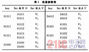
As can be seen from Table 1, the wire harness with the line number 91311 is composed of the segment of the wire that the vertices are V1 and V3. Similarly, a wire harness with line number 24012 consists of a segment of the wire that the vertices have crossed for V3 and V4. Other wire harnesses are structured in such a way. The connected loop set as shown in Fig. 8 can be drawn through the connectivity parameter table to simplify Fig. 1 and intuitively find the harness to be identified.
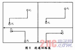
The connected loop is concentrated, and the portion between each two nodes is called a bundle segment. The lengths identified by the segments are added during the computer identification process to determine the length of the desired harness.
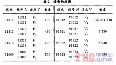
2.3.5 Output Results The connected parameter table and the connected loop set simplify Figure 1 into four sets of harnesses, namely the bundle set V1-V3, the bundle set V2-V3, the bundle set V3-V4 and the bundle set V3-V5. As can be seen from FIG. 2, V1-V3 is composed of two segments, and in combination with FIG. 1, the length of the V1-V3 harness set is 230+260=490. Similarly, the V2-V3 harness set consists of three segments, with a length of 200+340+260=800. The V3-V4 harness set consists of four segments, which are 260+340+910+60=1 570 and 260+340+91O+200=1 710 according to the wire diameter requirements of the fourth segment. The V3-V5 harness consists of four segments, with a length of 260+340+910+1 020=2 530.
2.3.6 Result Output Through the above ideas, the computer can obtain the length of the harness by comparing the connected parameter table. As shown in table 2.
3 Conclusions This paper makes a preliminary study on the identification of the segment of the wire harness in the wire harness drawing. According to the method of this paper, the automatic identification of the wire segment in the drawing can be realized. This identification method improves the production efficiency of the automobile industry in China and reduces the operation of personnel. Error rate. However, considering the large amount and complexity of the information contained in the wiring harness drawings, in order to better integrate the software with the comprehensive intelligent application of actual production, to achieve the automatic extraction of the drawing information and the goal of automatically establishing the wire harness process model, it is also necessary to automatically The identification method is further studied and explored. After investigation, a lot of research work has been done at home and abroad to convert hand-drawn engineering drawings into CAD drawings and to identify and understand them. You can learn from these tasks to more effectively identify automotive wiring harness drawings.
Traffic Facilities,Waterproof Traffic Facilities,Outdoor Traffic Facilities,Traffic Control Devices
Yangzhou Heli Photoelectric Co., Ltd. , http://www.heli-eee.com