Improperly driving a stepper motor can easily cause the motor to emit "beep" noise and large vibrations.
When the stepper motor is driven, if the stepper motor is found to be at rest, its internal noise is very obvious, which is similar to the rapid change of the coil, which is generally caused by excessive coil current. For this case, the most effective method of connection is to reduce the current flowing in the motor coil. The specific method includes: setting the driver to automatically flow half-flow when the motor stops, reducing the driving current of the motor. Due to the working mode of the stepper motor, the state of the stepper motor is always changed by the internal coil.
When driving the stepper motor, if the stepper motor noise and vibration are found to be obvious, check the following steps:
1. Whether the stepping motor and the driver are matched, this is very important: if they are not matched, the adjustment subdivision, driving current and speed of the following steps are likely to be in vain. In my own experience, I have encountered this situation. The Raytheon motor is driven by a different brand of drive. Under the same conditions, it always produces obvious noise and vibration, and drives the machine. The structure makes a loud noise. Similarly, using a Raytheon drive to drive some other manufacturers' stepper motors also produces a lot of noise and vibration. Therefore, it is recommended that when you choose stepper motors and drivers, it is best to buy them in sets, and make sure that you buy regular products. Now the same type of drive on the market, there are many manufacturers. For example, DM542, more formal, there are Ankete and Lei Sai.
2, the current stepper motor driver is divided into digital and analog, the analog drive stepper motor is more noisy, and the digital is basically not. The reason is roughly that a digital DSP is added to the digital motor for stepper motor drive optimization. Therefore, if you want to ensure that the noise and vibration are as small as possible, it is recommended to use a digital stepper motor driver.
3. Correctly adjust the subdivision and current of the stepper motor driver. The larger the subdivision, the smaller the variation of the coil in the motor, which will reduce the noise. The subdivision is generally recommended to be set in 8 subdivisions and above. If the table lookup method is used to calculate and control the speed during acceleration and deceleration and uniform speed, it is very easy for a general MCU. In the case that the stepping motor has enough torque to drive the load, the driving current should also be reduced as much as possible. The smaller the parameter is set, the smaller the variation of the coil current in the motor.
4, correctly set the stepper motor acceleration and deceleration, the highest operating speed. Experiments have shown that stepper motors are more prone to additional noise during acceleration and deceleration. The solution is to increase the acceleration and deceleration speed of the stepping motor under the condition that the stepping motor accelerates and decelerates without losing step. Under light load conditions, the stepping motor's acceleration and deceleration should be controlled within 1S, otherwise the noise caused by the change of the drive current frequency will be heard when the motor is accelerated or decelerated. When setting the maximum operating speed, it is necessary to consider whether the motor torque is sufficient to drive the load, and whether it will resonate with the connected mechanical structure at this speed.
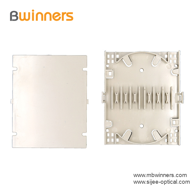
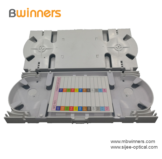
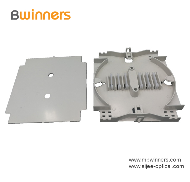
FTTH Fiber Optic Splice Tray is designed to provide a place to store the fiber cables and splices and prevent them from becoming damaged or being misplaced. It is also called a splice enclosure or splice organizer. This device does not contain any technical functions, and the design is simple. Also, Fiber Optic Tray has a very low price for people to afford. However, the importance of fiber splice tray for protecting fibers is significant. And the skills needed for using a fiber splice tray is not as simple as you think.
Made by industrial high-quality ABS plastic, Fiber Optic Cable Tray is provided to place the fiber splice points and pre-terminated for fiber connectivity. The splice tray expands fiber splice capabilities as well as provides the splicing location for fiber optic cables. It can be put into the fiber distribution frame, fiber splice closure, optic terminal box, etc. Sijee offers different shapes of fiber splice tray with or without termination function. Fiber Optic Tray, Fusion Splice Box, Fiber Optic Cable Tray, Splice Tray Optic Fiber are available.
Applications:
Fiber splice trays are usually placed in the middle of a route where cables are required to be joined or at the termination and patch panel points at the end of the cable runs. Also, splices can be placed in a splice tray which is then placed inside a splice closure for OSP (outside plant) installations or a patch panel box for premises applications. As for indoor application, fiber splice trays are often integrated into patch panels to provide for connections to the fibers.


Fiber Optic Tray,Fusion Splice Box,Fiber Optic Cable Tray,Splice Tray Optic Fiber
Sijee Optical Communication Technology Co.,Ltd , https://www.sijee-optical.com