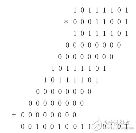
Addition, subtraction, multiplication and division are the basis of the calculations, and they are also the key compulsory courses in the primary school classroom. Although the multiplication and division operation is still a piece of cake for us today, letting the computer do a lot of work is not enough. But if you really want to explore how the computer completes the division and calculation, there are some learning and skills, not the human brain. 9 flashed past 81, and although the computer may get results faster than people, it doesn't know how many orders of magnitude, but it still needs a process. It is possible that the internal computing principles and mechanisms of the different CPUs are slightly different. We can't completely clarify these computing methods. In this routine, we honestly complete two 8-bit unsigned numbers by shifting and accumulating. Multiplication operation. Here we will give an example of our operation principle, such as 8-bit unsigned number 189 and 25 multiplication. Because computers only know 0 and 1, the basis of all operations is 0 and 1, so our operations must also be based on binary. Therefore, we must first complete the conversion of the mechanism. The binary number corresponding to the multiplier 189 is 10111101, and the binary number corresponding to the multiplicand 25 is 00011001. According to our most commonly used decimal multiplication, we can get the binary multiplication shown in Figure 1. In this operation, we judge whether the value is 1 or 0 from the lowest bit to the highest bit of the multiplicand. If it is 1, it accumulates the multiplier, otherwise it does not accumulate (that is, takes 0), and the accumulated multiplier is needed. According to the current multiplicand bit, the corresponding shift is needed. If the bit 3 of the multiplicand is 1, the multiplier is shifted to the left by 3 times (that is, amplified by 8 times) as the accumulated number. According to this principle, the 8-bit unsigned multiplication we want to design is also the final result by multiplying the multiplicand by the bitwise judgment and then accumulating the left shift.
The operation enable signal. 0 means no operation; 1 means multiplication of the currently input ain and bin.
8-bit unsigned number, which will be multiplied by bin.
8-bit unsigned number, which will be multiplied by ain.
A 16-bit unsigned number used to store the result of multiplying two 8-bit unsigned numbers.
The multiplication operation completes the flag bit. After the current operation is completed, the output is high, and if the enable signal is pulled low, the signal is also pulled low.
Shift counter, when enable=1, each clock cycle i will increment until i=8 stops. When i=0~7, the shift accumulation calculation is performed correspondingly.
General Purpose Rectifier Bridge
A bridge rectifier provides full-wave rectification from a two-wire AC input, resulting in lower cost and weight as compared to a rectifier with a 3-wire input from a transformer with a center-tapped secondary winding.
Our company mainly produces diodes, which are sold overseas.Has a stable source of customers, product quality by customers trust.
Our products are the ideal choice of printed circuit board, we have reliable low-cost construction technology, product price cost-effective, welcome to come to consult.

Bridge Rectifiers,GBU General Purpose Rectifier Bridge,General purpose Rectifier diodes,General Purpose Bridge Rectifiers
Changzhou Changyuan Electronic Co., Ltd. , https://www.cydiode.com