With the development of electronic technology, many intelligent technologies are widely used in vehicles, and vehicle rearview mirror systems as important safety auxiliary devices have also experienced several generations of technical development [1]. At present, two new technologies have appeared in the vehicle rearview mirror system: rearview camera and reversing radar. The former image is intuitive and true, but it can not give an accurate distance; the latter can accurately measure the distance, but it can not reflect the puddles behind the car, the protruding steel bars, etc., so there is a dead end in safety [2] [ 3]. There are several types of radar ranging on vehicles: laser ranging, microwave ranging and ultrasonic ranging. The first two have a long measuring distance and high measurement accuracy, but the cost is high; the latter has a low cost, but the range is usually small, and the safety is not good when the reversing speed is slightly faster.
This paper proposes a vehicle electronic rearview mirror system based on SOPC technology. The system can display the image behind the vehicle in real time, and uses dual-frequency ultrasound to achieve a large range of more than 10m. At the same time, the system has voice broadcast measurement results and Alarm and other functions.
1 System characteristics
Compared with other electronic reversing systems, this system has the following features: (1) Ultrasonic distance measurement with two frequencies of 40kHz and 25kHz, which not only expands the measurement range but also takes into account the measurement accuracy when measuring in a small range. (2) A 3.5-inch color LCD screen can be used to display the image behind the vehicle in real time and intuitively, while displaying the distance of the obstacle and the speed of the vehicle relative to the obstacle. (3) Voice broadcasts the ranging results and alarms. The voice chip ISD4002 is used to realize the voice broadcast of the distance measurement result, and at the same time, the danger level is automatically evaluated according to the measurement result and the speed of the vehicle relative to the obstacle, and the warning sounds with different urgency levels are used to warn. (4) Adopt SOPC to realize system design, which has good flexibility.
2 Hardware circuit design
2.1 System hardware structure
The circuit block diagram of the vehicle's electronic rearview mirror system is shown in Figure 1. The whole system can be divided into image acquisition and conversion, image and information display, ultrasonic ranging, voice broadcast and warning, temperature measurement and other parts. The CMOS image sensor OV6620 sends the collected image data to the FPGA. After processing, the data in RGB888 format is obtained and sent to the LCD screen for display via the LCD control circuit. The ultrasonic ranging circuit has two channels on the left and the right. It uses two ultrasonic pulses with a frequency of 40kHz and 25kHz to measure the distance of obstacles and the relative speed of the vehicle, and then performs a risk assessment and then displays the relevant information on the LCD screen, and broadcasts the distance measurement. As a result, the alarm circuit is then controlled to emit warning sounds with varying degrees of urgency. 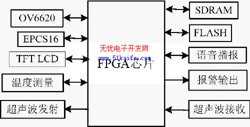
Figure 1 Block diagram of system hardware structure
1. 2.2 Design of main functional modules
2. 2.2.1 Image acquisition and conversion circuit
The block diagram of the image acquisition and conversion circuit is shown in Figure 2. The YCrCb4: 2: 2 format data output by the image sensor OV6620 is converted into YCrCb4: 4: 4 format data by the deinterleaving circuit, and sent to the color space conversion circuit to complete the data format conversion, and then stored in the buffer RAM. The following focuses on the color space conversion circuit.
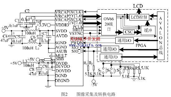
The image sensor ov6620 outputs data in YCrCb4: 2: 2 format, and the LCD screen used in the design requires input of RGB888 format data, so a color space conversion circuit is required to complete this conversion. The conversion formula is shown in equation (1).
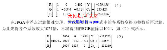
The RGB in the conversion result is an 8-bit unsigned number, with a value range of 0 to 255, so the operation result is 0 for negative numbers; the operation result exceeds 255 and 255. This will introduce errors, but it has little effect on the display of the image. Using VerilogHDL to complete the design of the circuit, when the YCrCb values ​​are 197, 92, and 232, respectively, the GRB output (with delay) is 186, 146, and 255, which is consistent with the results calculated according to (1).
2.2.2 Ultrasonic wave transmitting and receiving part If higher frequency ultrasonic wave is used in ultrasonic ranging, it will decay faster due to larger air absorption, so the measuring distance is shorter. For example, using 40kHz ultrasonic wave, the range of measurement generally does not exceed 5m. Since the absorption of ultrasonic waves by air is proportional to the square of the ultrasonic frequency, reducing the frequency of ultrasonic waves can increase the range of the distance measurement. But if the frequency is too low, the absolute error of distance measurement is larger [4]. In order to take into account both the range and accuracy of the distance measurement, two ultrasonic distance measurements of 40kHz and 25kHz are used in the design. The measurement principle is: first output 10 40kHz ultrasonic pulses, and then output 8 25kHz ultrasonic pulses. Because high-frequency ultrasonic waves are sent out first, for the same target, the echo reaches the CPU first, so for short-range targets, first use high Low-frequency ultrasonic detection, the absolute error of measurement is small; for distant targets, the high-frequency ultrasonic wave is absorbed by the air and greatly attenuated, so the echo is only low-frequency ultrasonic. Acceptable. The received ultrasonic signal is sent to the PIO port of NiosII after processing such as amplification and comparison, and the PIO port is interrupted. The ultrasonic propagation time is obtained by executing the interrupt service program, and then the distance of the obstacle is calculated according to the measured ambient temperature. Calculate the relative speed between the two measurements. Only 25kHz ultrasonic transmitting and receiving circuits are shown here, as shown in Figure 3.
2.2.3 LCD display control circuit

This design uses Samsung's 3.5-inch TFT LCD screen with a resolution of 320 & TImes; 240 (model LTV350QV-F04). The design divides the display into two parts: the upper 16 lines are used to display the measured distance, speed, current status And other information, the lower 224 lines show the image behind the vehicle. In order to improve the display refresh rate and reduce the CPU occupancy rate, the LCD display control is implemented by a hardware circuit, and the circuit block diagram is shown in FIG. 4. The controller uses the line sync signal, field sync signal, pixel clock and other signals output by the OV6620 to generate the control signals needed to control the LCD screen; in addition, the controller includes a line sync signal counter and dual-port RAM address generator, both It is cleared when each field signal arrives, and then the line counter counts the line synchronization signal. When the count value is between 16 ~ 240, the controller sends the image data in the data buffer to the LCD module, when the count value is 0 ~ At 15 o'clock, the data in the dual-port RAM is read out sequentially and sent to the LCD screen for display. The dual-port RAM in the block diagram is write-only for the microcontroller. After the presence signal arrives and is delayed for a period of time (greater than the LCD completes 16 lines of data display time), NiosII will update the measured obstacle distance, speed, etc. The display data is written into the dual-port RAM; for the LCD controller, the dual-port RAM is read-only, and the data is read only at the beginning of each line of 16 lines, so there will be no conflicts between read and write. This design greatly reduces the occupancy rate of the NiosII processor, so that the system has enough time to complete other tasks.
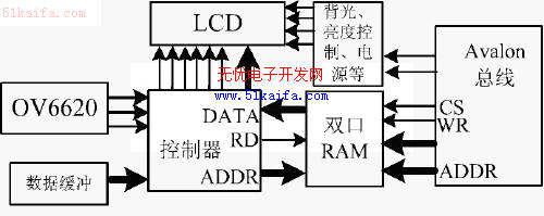
Figure 4 LCD display control circuit block diagram
2.2.4 Voice playback and temperature measurement circuit
The voice playback circuit is mainly composed of the recording and playback circuit ISD4002 and the power amplifier circuit LM386. NiosII simulates the SPI timing through the I / O port to realize the control of ISD4002, and handles the playback of each segment in ISD4002 in an interrupted manner, thereby achieving continuous playback of voice. The temperature measurement circuit is mainly composed of a digital temperature sensor LM75. 3 Design of system software
The software of this system is relatively complex, and due to space limitations, only the ultrasonic measurement module is briefly introduced here. When the ultrasonic measurement module is executed, the number of measurements is counted first. If all channels have completed two measurements (the relative speed is calculated from two consecutive measurements), a measurement cycle ends. In a measurement cycle, the time stamp timer T0 is read before each measurement, and the time difference is obtained from the reading result to obtain the relative speed. When sending ultrasonic waves, first send a high-frequency wave of 40kHz, and then send a low-frequency wave of 25kHz. If the returned ultrasonic signal is not received within 50ms, it means that the range is exceeded and the next channel is measured.
System implementation and testing
Using Altera's DE2 development board as the experimental platform, the design verification of this system was completed by using two general-purpose I / O expansion slots connected to the experimental circuit board on the platform. Experiments show that for flat objects, the minimum ultrasonic range of the system is 7cm, the maximum measurement range is greater than 10m, and the measurement error is not more than ± 1cm when the distance is within 2.5m; the voice prompt is clear, and the image displayed on the LCD screen is clear and stable. The working condition of the system is shown in Fig. 7, which indicates that the distance to the obstacle (vehicle in Fig. 5) is 6.51m, the speed is 0.65m / s, and it is currently in the state of exposure time adjustment. The negative value of the speed indicates approaching. 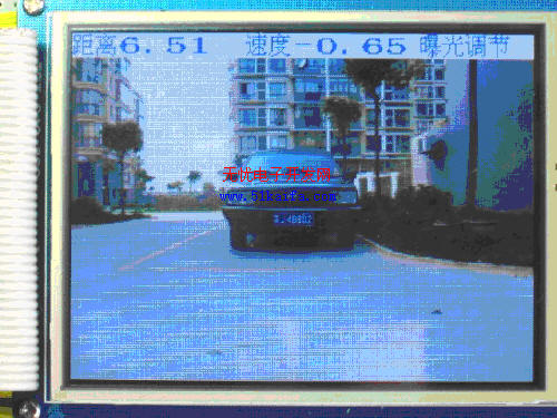
Figure 5 System work
Conclusion
This paper uses SOPC technology to design a vehicle electronic rearview mirror system. The system uses CMOS image sensors to collect the image of the rear of the vehicle and display it on the LCD screen in real time. At the same time, it uses dual-frequency ultrasound to achieve a wide range and high precision ranging. The driver can timely, accurately and comprehensively grasp the situation behind the vehicle, which greatly improves the safety of reversing.
The author of this article innovates: applying dual-frequency ultrasonic ranging to reversing radar, expanding the range of general ultrasonic reversing radar; organically combining rear-view camera and ultrasonic ranging to design a more complete vehicle Electronic rearview mirror system.
Foresee more exciting information about the rearview mirror, please poke right: http: //
Touchless Sensor-Makes it germ Free
Environment Friendly-Prevents Contamination
Ideal fit for Kitchen/Bathroom/Bedroom
As users hands or debris enter the zone 6 inches (15cm) from the infrared sensor on top of the dustbin, the lid will automatically open.
The Lid will remain open if hand or debris is within the 6 inch (15cm) range of the infrared sensor. Lid will close 7 seconds after users hands move away.
The new touch switch panel has higher stability and efficiency. you can use it effortlessly. There are [OPEN" & [CLOSE" buttons for manual operation, and there is a ON/OFF power switch on the back of the dustbin.
The new removable plastic rim is easy to lift out, and the plastic ring helps leave no excess plastic bag visible (w/o liner).
Two liners (30L+20L) for easy recycling
Features:
-100% [Hands-Free" operation.
-[Germ-Free"-Prevents cross-contamination
- Trash Bag Retainer Ring stops full, heavy bag from falling in and keeps bag ends neatly out of view
-Rubber feet keeps this trash can in place and protects floors from scratches
-Removable hard ABS plastic head for easy cleaning
-Uses 4 AA-Sized batteries 1.5V(LR6) (Not included)
-Low energy-consuming
-Multiple colors to satisfy your different requirements.
-Capacity:30L+20L
-Dimensions: 34W x 48 L x 64H CM
-1 Year Manufacturer`s Warranty included
Rectangular Sensor Automatic Dustbin 2-Compartment 30L+20L
Automatic Dustbin,Hand Sensing Dustbin,Hotel Dustbin,Environmental Dustbin
NINGBO ZIXING ELECTRONIC CO.,LTD. , https://www.zixingautobin.com