Overview The DS31256 HDLC controller accesses HDLC packets sent and received via the PCI bus. This application note discusses how to calculate the bus bandwidth required for the DS31256 to function properly. Definitions of related terms involved are given at the beginning of this article.
According to the information provided in this application note, users only need to adjust some data in the quick calculation table (available on request), and then it can be used in specific applications.
Table 1. Definition of variables involved in this application note
| Variable | DefiniTIon | Valid Range |
| B | Average number of packets processed before the host updates the receive free queue and transmit pending queue or reads the receive done queue and transmit done queue | 1, 2, 3,.... |
| C | Average number of bus cycles required per packet | 1, 2, 3,.... |
| D | Number of bus cycles needed for data to be transferred | 1, 2, 3,.... |
| P | Packet size in bytes | 64 |
| R | Average number of bus cycles added due to latency in RAM access | 0, 1, 2,.... |
| X | Average number of bus accesses required to send or obtain packet data to, or from the data buffers | 1, 2, 3,.... |
The bus access type DS31256 or the host performs four types of bus access to support direct memory access (DMA) within the DS31256. In the following discussion, variable D is defined as the number of data cycles, and variable R is defined as the number of bus cycles required due to RAM access time.
Access type 1: DMA burst read host RAM The total number of bus cycles required when DMA burst read host RAM is [3 + R + D]. This can be derived from Figure 1 and Table 2.
Table 2. Total number of bus cycles required for DMA read
| Cycle | No. Cycles Required |
| Address Cycle | 1 |
| Turnaround Cycle | 1 |
| RAM Access Latency Cycle | R |
| Data Cycle | D |
| Turnaround Cycle | 1 |
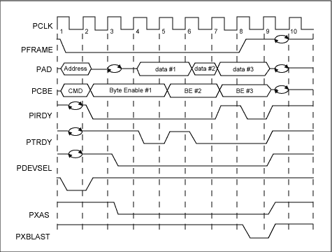
Figure 1. DS31256 PCI bus read
Access type 2: DMA burst write to host RAM The total number of bus cycles required when DMA burst writes to host RAM is [2 + R + D]. This can be obtained from Figure 2 and Table 3.
Table 3. Total number of bus cycles required for DMA write
| Cycle | No. Cycles Required |
| Address Cycle | 1 |
| RAM Access Latency Cycle | R |
| Data Cycle | D |
| Turnaround Cycle | 1 |
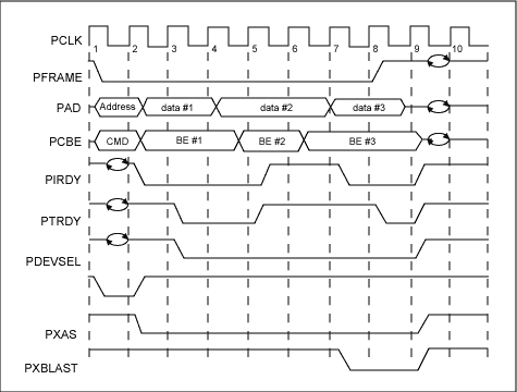
Figure 2. DS31256 PCI bus write cycle
Access type 3: Host writes to the DS31256 The total number of bus cycles required by the host to write to the DS31256 is 7.
Access type 4: The total number of bus cycles required by the host to read the DS31256 when the host reads the DS31256 is 7.
Note: For access types 3 and 4, 7 access cycles are inherent to DS31256 and cannot be changed.
The number of bus cycles required for each packet is to calculate the bus utilization rate. First, the number of bus cycles required must be known. In order to obtain this data, we made some assumptions listed in Table 4. Figure 3 shows the standard process that the host and DMA will perform when a packet is received or sent. According to Figure 3, it is possible to derive a formula to calculate the average number of bus cycles required for each packet, which is the variable C.
The sending side period on the sending side = read waiting queue + write horizontal descriptor chain + read descriptor + read packet from host memory + write completion queue + read / write register.
Ct = [(3 + R + 12) / 12] + [2 + R + 1] + [3 + R + 4] + [(P / 4) + (3 + R) X] + [(2 + R + 6) / 6] + [4 (7 / B)]
Receive side Receive side period = read free queue + write packet to host memory + write descriptor + write completion queue + read / write register.
Cr = [(3 + R + 24) / 12] + [(P / 4) + (2 + R) X] + [2 + R + 3] + [(2 + R + 6) / 6] + [ 4 (7 / B)]
The total formula Ct + Cr = 21.16 + 3.5R + 0.5P + (5 + 2R) X + 56 / B
Table 4. Assumptions to facilitate calculation of the number of bus cycles required per packet
| 1 | All packets are 64 bytes (seen as worst case). |
| 2 | The Frame Check Sequence (FCS) of the HDLC packet is not transferred to, or from the PCI bus. |
| 3 | On the receive side, only large buffers are used (small buffers are disabled). |
| 4 | The receive DMA will burst read the free queue and burst write the done queue. |
| 5 | The transmit DMA will burst read the pending queue and burst write the done queue. |
| 6 | All packets fit within a single buffer (ie, only one descriptor). This is reasonable because packets are 64 bytes. |
| 7 | All physical layer links are filled with packets; no idle codes are sent or received. |
| 8 | Interrupt rouTInes and overhead (like accesses to the local bus) are not considered. |
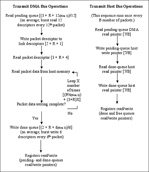
Figure 3. Bus processing flow for each packet
Note: 12 descriptors x 1 double word = 12 send wait queue descriptor double word packet data bytes = 4 bytes / data cycle 6 descriptors x 1 double word = 6 send complete queue descriptor double words
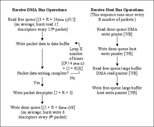
Figure 3. (Continued)
Note: 12 descriptors x 2 double words = 24 receive free queue descriptor double word packet data bytes = 4 bytes / data cycle 6 descriptors x 1 double word = 6 receive completion queue descriptor double words PCI bus utilization Bus utilization is defined as the number of bus cycles required by the DS31256 per second divided by the total number of bus cycles available per second. Bus utilization can be calculated according to specific HDLC configuration and traffic. The calculation assumes that the PCI bus clock rate is 33MHz (33,000,000Hz), and only one DS31256 is used. The following is a detailed calculation method of PCI bus utilization.
Formula 1:

Formula 2:

Note:
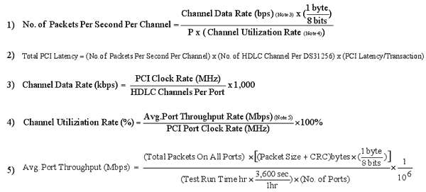
For example, laboratory measurement results on the utilization rate of the PCI bus show the use of the PCI bus of the DS31256. It is assumed that all received and sent data packets are 56 bytes long (P = 56). The results are summarized in Table 5. We have also made a quick calculation table (as shown in Table 6) that can calculate the bus utilization rate, and can request it if necessary (please contact var name = "telecom.support @"; var domain = "maxim-ic.com"; document .write ("" + name + domain + ""); telecom. (English only).)
Table 5. PCI bus utilization laboratory measured data
| B | P | R | |||||||
| Mode | No. of Ports | Avg. No. Done Queues Entries Processed | Pkt Size (Bytes) | Avg. RAM Access Latency Cycles | No. of HDLC Channels | Total No. of Channels | Channel Data Rate (kbps) | PCI Clock Rate (MHz) | PCI Bus UTIl. (%) |
| High Speed | 3 | 14.17 | 56 | 8.35 | 1 | 3 | 52 | 52 | 47.55 |
| Unchannelized | 3 | 35.53 | 56 | 8.50 | 1 | 3 | 29 | 29 | 49.06 |
| Low Speed | 16 | 100.46 | 56 | 10.60 | 1 | 16 | 12 | 12 | 55.27 |
| Unchannelized | 16 | 24.30 | 56 | 10.24 | 1 | 16 | 10 | 10 | 52.54 |
| T1 | 16 | 8.081 | 56 | 7.1375 | 12 | 192 | 128 * | 1.544 | 18.26 |
| E1 | 16 | 8.154 | 56 | 7.8645 | 16 | 256 | 128 | 2.048 | 28.07 |
| 2E1 | 16 | 10.894 | 56 | 8.003 | 16 | 256 | 256 | 4.096 | 55.82 |
| 4E1 | 16 | 381.207 | 56 | 8.3123 | 8 | 128 | 1024 | 8.192 | 50.97 |
* Note: Each T1 frame has 193 bits = [(24 time slots x 8 bits) + 1 sync bit] The data rate of each time slot is 64,000 bits / second (64,000 bits / second) / 8 bits = 8,000 frames / Sec arrives every 125 microseconds T1 frame = 1 / (8,000 frames) / sec data rate is 1,536,000 bits / sec = 24 channels x (8 bits / channel / frame) x (8,000 frames / sec) total line rate is 1,544,000 bits / Sec = [(24 channels x (8 bits / channel)) + (1 sync (bits / frame))] x (8,000 frames / sec) Table 6. DS31256 PCI bus utilization speed calculation table
| Input Variables | ||
| B | 14.17 | The average number of packets processed before the host updates the Receive Free Queue and Transmit Pending Queue, or reads the Receive / Transmit Done Queues. |
| P | 56 | The size of the packet in bytes. |
| R | 8.35 | The average number of bus cycles added due to latency in RAM access. |
| Number of HDLC channels per DS31256 | 3 | Use 1 per acTIve port when operating in unchannelized mode. |
| Channel Data Rate (kbps) | 52,000.00 | Note that T1 speed == 1536kbps. |
| Channel Utilization Rate | 39.5% | There can be time between packets in real applications. |
| PCI Clock Rate (MHz) | 33 | |
| PCI Latency / Transaction | 10 | This is based on the average number of cycles required to perform each of the transactions associated with processing a packet. Our designers use 10 in their simulations, which is fairly conservative. |
| Number of DS31256's on Bus | 1 | |
| Intermediate Variables | ||
| C | 104.04 | The average number of bus cycles required per packet. |
| X | 1.00 | The average number of bus accesses required to send / obtain packet data to / from the data buffers. |
| Packets / second / channel | 45,871.43 | |
| Total PCI Latency | 1,376,142.86 | |
| No. of Bus cycles required / sec | 15,693,122 | |
| Half Duplex | Full Duplex | |
| Bus utilization | 47.6% | 95.11% |
| Bus Capacity (Mbps) | 264 | |
| Bus Throughput (Mbps) | 125.54 | 251.09 |
Note:

Among them, 1024 blocks is the size of the FIFO, and the high and low watermarks of the FIFO are set at 50%.
Conclusion This application note explains how to calculate the bus bandwidth requirements of the DS31256 in a given application. Some examples of laboratory tests are provided. And provide an electronic quick calculation table that can perform this kind of calculation, can be obtained if necessary.
Computer Vacuum Cleaner: This mini vacuum cleaner is used for cleaning computer, notebook, keyboard, etc. With strong function, the vacuum cleaner can clean every small dust on the computer or inside the keyboard very well.
You don`t need to worry the storage, because the vacuum cleaner body is small, it can be stored in a small space you like. By the way, this Small Vacuum Cleaner is cordless Usb Vacuum Cleaner and very easy to use.
For charging, this Portable Vacuum Cleaner is also very easy and convenient. And not only for cleaning computers, the wireless vacuum cleaner also has many other cleaning functions.
This Rechargeable Vacuum Cleaner will be a good helper to help you clean the corners in the house or other places.
Computer Vacuum Cleaner
Usb Keyboard Vacuum,Mini Usb Vacuum Cleaner,Pc Vacuum Cleaner,Computer Vacuum Cleaner Anti Static
SHENZHEN HONK ELECTRONIC CO., LTD , https://www.honktech.com