Keywords: vector network analyzer, swept frequency signal source, direct digital frequency synthesis
1 Introduction In radio measurement, it is often necessary to measure the frequency characteristics of equipment or networks. Vector network analyzers are used to measure the frequency characteristics of two-port linear time-invariant networks, including amplitude-frequency response and phase-frequency response. The key to measuring frequency characteristics is to generate a frequency stepped signal source. The frequency, amplitude, and phase of the signal source should be accurately determined. In the past, most frequency-swept signal sources were based on voltage-controlled oscillators (VCO), function generators, and phase-locked loop (PLL) technologies. These technologies have the problems of long conversion frequency, low frequency accuracy, and relatively large hardware consumption. With the rapid development of ultra-large scale integrated circuits, a DDS frequency sweep signal source composed of a single-chip microprocessor and a direct digital frequency synthesis (DDS) chip has emerged at the historic moment. Compared with other frequency synthesis methods, the main advantages of DDS technology are: high resolution; fast frequency conversion; phase switching during frequency switching; continuous synthesis frequency; accurate digital control; can be interfaced with a microprocessor. The improvement of DDS on signal quality is that the phase noise of its system mainly depends on the reference clock oscillator, which is basically not affected by other parts of the system. Now, DDS technology has been widely used in local oscillator, signal generator, instrument, communication, radar and other systems.
2 Direct digital frequency synthesis (DDS) technology Direct digital frequency synthesis DDS (Direct Digital Synthesis) is a novel frequency synthesis technology. The realization of this technology depends on the generation of high-speed digital circuits. At present, its working speed is mainly limited by the D / A converter. DDS technology is to use the characteristics of the linear relationship between the phase of the sinusoidal signal and time to obtain the instantaneous amplitude of the signal by means of table look-up, thereby achieving frequency synthesis. In order to output a signal of a certain frequency, in each clock cycle, the phase increment value ΔPhase stored in the frequency / phase word register is sent to the phase accumulator, and the output result is sent to the sine and cosine function tables. Convert the phase information to the corresponding sinusoidal amplitude value to produce a digitized sinusoidal signal. The relationship between the phase increment value ΔPhase and the output signal frequency fout and fc reference clock frequency is
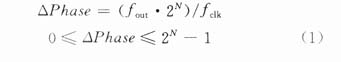
In the type, N is the word length of the phase accumulator. Known by formula (1), the phase increment value ΔPhase is proportional to the output signal frequency fout.
According to the sampling theorem, the frequency of the signal generated by DDS cannot exceed half of the clock frequency. In practice, in order to ensure the output quality of the signal, the output frequency should not be higher than 33% of the clock frequency to avoid aliasing or harmonics falling into useful Within the output frequency band.
The frequency resolution fstep of the swept signal source directly depends on the frequency resolution Δf of the DDS, and the calculation formula is as follows


The frequency sweep range of this instrument is 1mHz ~ 2MHz, the ADDS DDS chip AD9850 of American AD company is used, and the single chip microcomputer is used as the controller to realize frequency synthesis and control. The AD9850 chip includes a 32-bit phase accumulator, a sine and cosine look-up table, and a 10-bit high-speed digital-to-analog converter. The core is the phase accumulator. The maximum clock reference frequency of the chip is 125MHz. For this frequency, the frequency accuracy of the output sine wave is 0.029Hz; the control interface is simple, and the control data can be input using an 8-bit parallel interface or a serial interface; 40-bit control words, of which 32 bits Frequency control word, 5-bit phase control word, 1-bit power sleep function, 2-bit manufacturer reserved test function; allow output phase to 180 °, 90 °, 45 °, 22.5 °, 11.25 ° or a combination of these phases Change for increment; advanced CMOS process not only makes AD9850 excellent performance, but also low power consumption, when + 3.3V power supply, power consumption is only 155mW; connected to a precision clock source, AD9850 can produce pure spectrum, frequency, phase programming control Analog sine wave output.
A single-chip microprocessor is used to control the DDS, and the circuit that constitutes the frequency sweep signal source is very simple. The circuit block diagram is shown in Figure 2.
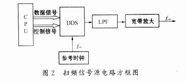
The circuit consists of a single-chip microprocessor (CPU), DDS, reference clock, low-pass filter (LPF) and broadband amplifier circuit. The low-pass filter is a key component in the frequency-sweeping signal source and is responsible for filtering out high-frequency spurious and harmonic signals contained in the output signal. There are three main sources of DDS output spurs: the N-bit phase accumulator only outputs the upper M bits to address the ROM; the amplitude code stored in the ROM is only limited bits; the limited resolution and nonlinear characteristics of the DAC; the output of the DDS Including the basic pulse harmonic spectrum, it appears in the following locations:
Kfclk ± fout K = 1, 2, 3LL
The author designed a 1mHz ~ 2MHz low-frequency vector network analyzer. The highest output frequency is 2MHz. A 50MHz reference clock is used to keep the harmonic signal frequency away from the output signal frequency and reduce the requirements for low-pass filters. The author designed a 7th order ellipse filter and achieved good results. The broadband amplifier selects a low-noise op amp to amplify the signal output by the DDS to meet the requirements of a frequency-swept signal source.
The single chip microprocessor can be used to control the logic and output signals of DDS in real time. The author chooses the MCS-51 series chip AT89C51 produced by Intel Corporation. The CS signal of AD9850 is obtained by address decoding. The W-CLK and FQ-UD signals are directly given by the P1 port of 89C51. In the program, it is necessary to strictly follow the timing requirements of AD9850. The software flow chart is shown in Figure 3 (using the parallel interface method as an example).
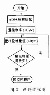
In Figure 3, the initialization of the AD9850 is the reset of the DDS chip. After reset, the registers except the input registers are cleared, the output becomes high impedance, and the high level of the reset pulse is maintained for at least 5 clock cycles. The control word defines whether phase modulation, low power consumption selection and setting mode. The phase increment value is calculated by formula (1).
DDS is a new generation of frequency synthesis technology that has emerged in recent years. The author has several suggestions for practical reference: in the program design, pay attention to the timing requirements of DDS, correctly send the logic control word, phase increment value; DDS is super large CMOS devices have relatively high requirements on the quality of the clock signal. The rising and falling edges of the clock signal should be free of large spikes and pits. The clock signal should be shielded with a ground wire; The chip automatically enters the power sleep mode. Above this frequency, the system returns to normal; consider a good decoupling circuit, the decoupling capacitor should be as close as possible to the device, pay attention to good grounding, and separate analog and digital grounds.
4 Conclusion This article introduces the basic principles of direct digital frequency synthesis (DDS) technology, and gives a system composition and implementation method of using DDS to realize the frequency sweep signal source in the low-frequency vector network analyzer. Direct digital frequency synthesis (DDS) technology has many advantages, such as: DDS output stability depends on the stability of the clock source; DDS is an open-loop system, no feedback link, its frequency synthesis time is mainly determined by the output low-pass filter The delay time is suitable for occasions where frequency agility is required; DDS can achieve a frequency resolution of mHz; the signal output of DDS is a smoothly changing process, and its continuous phase is not possessed by other frequency synthesis. Many advantages of DDS meet the requirements of frequency-swept signal sources, but it also has certain disadvantages, such as: the output spectrum has large spurs; in addition, the output is limited by the operating frequency of the device. This subject 1mHz ~ 2MHz low frequency vector network analyzer applied AD9850 to the frequency sweep signal source, achieved good results, and achieved the expected goal.
references
Function: The Cob Work Light has 1-5 modes;
Feature: The COB Work Light usually higher power and super bright than LED Work Light;
Trait: The products are waterproof, shockproof;
Method of application: Simple on/off push button operation;
Range of application: The COB Work Light for emergency events, camping, outdoor activities and indoor;
Adervantages: Our products are saled with factory price, and the quality can guarantee, lastly we provide warranty for 1 year.
COB Work Light
Cob Work Light,Cob Led Work Light,Cob Led Flashlight,Cob Flashlight
Ningbo Henglang Import & Export Co.,Ltd , https://www.odistarflashlight.com