The MAX6958 and MAX6959 are 4-digit, 9-segment LED drivers which use a reduced pin count mulTIplexing scheme to drive 36 segments using only 10 drive pins (Table 1). This applicaTIon note discusses a technique to drive a 5th, additional digit. A 5th digit is required for counter display applications displaying numbers in the range -39999 to 39999. The technique described here enables the MAX6958 / 59 to drive five digits to display -39999 to 39999. The technique sacrifices the dp (decimal point) segments, so that measurement scaling can't be displayed. This approach is therefore best suited to counter applications where range dp segments are not needed.
The MAX6958 / 59 uses four multiplex cycles, as shown by Table 1. The driver is therefore a good fit for applications using four digits and four to eight discrete LEDs. The example schematic in Figure 1 shows the wiring connections of a MAX6958 or MAX6959 display to four 7-segment digits and eight discrete LEDs. If dp (decimal point) segments are needed for the four digits, then SEG 4 through SEG 7 can be wired to the dp segments of Digit 0 through Digit 3 respectively, instead of the four discrete LEDs as shown.
Table 1. Standard Driver Connection for the MAX6958 / 59
| DIG / SEG 0 Pin 4 | DIG / SEG 1 Pin 5 | DIG / SEG 2 Pin 6 | DIG / SEG 3 Pin 7 | DIG / SEG 4 Pin 11 | SEG 5 Pin 12 | SEG 6 Pin 13 | SEG 7 Pin 14 | SEG 8 Pin 15 | SEG 9 / IRQ Pin 3 | |
| LED Digit 0 | CC0 | SEG 0 | SEG g | SEG f | SEG e | SEG d | SEG c | SEG b | SEG a | SEG 4 |
| LED Digit 1 | SEG 1 | CC1 | SEG g | SEG f | SEG e | SEG d | SEG c | SEG b | SEG a | SEG 5 |
| LED Digit 2 | SEG g | SEG f | CC2 | SEG 2 | SEG e | SEG d | SEG c | SEG b | SEG a | SEG 6 |
| LED Digit 3 | SEG g | SEG f | SEG 3 | CC3 | SEG e | SEG d | SEG c | SEG b | SEG a | SEG 7 |
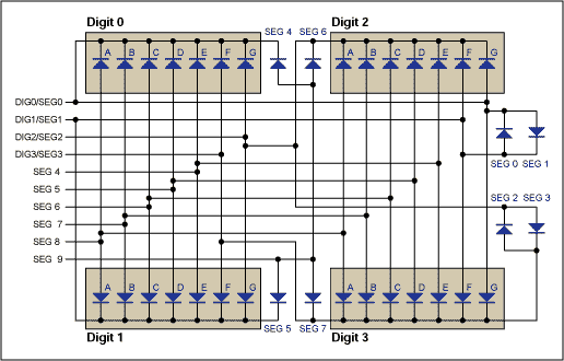
Figure 1. Typical application; the MAX6958 / 59 connections to four digits.
Although Figure 1 shows the four digits as separate displays, Digit 0/1 and Digit 2/3 can be a built using a pair of dual-digit displays instead of single-digit displays.
The four discrete LEDs SEG 0 through SEG 3 are wired to the driver in a fairly convoluted manner, as shown in Figure 1. As these four LEDs are not wired with a common anode or cathode, it is not possible to drive directly 4 segments of a fifth 7-segment digit instead of four discrete LEDs. However, as Table 1 shows, the four segments SEG 0 through SEG 3 are driven during different multiplex cycles. That means that all we have to do to drive a 5th digit is to ensure that the 5th digit's cathode is always driven by the appropriate cathode driver during each multiplex timeslot. Figure 2 shows how to do this with four diodes. The diodes simply steer whichever cathode drive output is low into the 5th digit's cathode.
The example circuit (Figure 3) is suitable for a 4-1 / 2 digit counter application whose leftmost (5th) digit only needs to display the numerals 1, 2, or 3. There is also provision to drive an additional segment to indicate negative . The last segment can be part of the 5th digit, or be a discrete LED.
The diode ORing scheme discussed earlier releases the four segments SEG 0 through SEG 3 to be used to drive a 5th digit. However, we need to drive seven segments; all but the 'f' segment of the 5th digit (to display numerals 1, 2, and 3) plus a negative indication segment. The only spare MAX6958 / 59 segments drives available are SEG 4 through SEG 9, which would normally operate the four dp segments which aren't used here. Unfortunately, these four segments are actually driven from the same MAX6958 / 59 pin, although during different portions of the 4-way multiplex to discriminate between them. So we can drive four segments, but they have to be wired in parallel, because they are going to have to be either all on together or all off together.
Luckily, this isn't a problem. When a numeral 2 or a numeral 3 is displayed, segments a, g, and d need to be lit (Figure 2). These segments need to be off in order to display numeral 1, when Segment b and c alone need to be lit. Numeral 3 also needs segments b and c, and numeral 2 needs segment e. So the wiring scheme uses SEG 4 through SEG 6 to drive segments a, g, and d in parallel, and SEG 0 through SEG 3 to drive segments 'negative', b, c, and e independently (Figure 3).
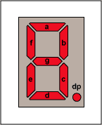
Figure 2. Segment labeling for 7-segment display.
Segment SEG 7 is unused, and must remain undriven by ensuring that bit D7 in register 0x24 is always 0. If D7 is set to 1, the three driven segments a, g, and d will be lit for Digit 4's multiplex period. Segments a , g, and d would then appear dimly lit (if they were set to be off by D6 = D5 = D4 = 0), or a little too bright (if they were set to be on by D6 = D5 = D4 = 1) . So what we end up with when segments a, g, and d are to be lit is that all three segments are on during the first three multiplex cycles (Digit 0 through Digit 2) and off during Digit 4's multiplex period. The three segments a, g, and d LEDs are wired in parallel, sharing current, so each gets 1 / 3rd the normal current, but for three multiplex cycles instead of one. Therefore each segment a, g, and d LED gets the same average LED current as all the other LEDs in the display, and all LEDs will light with the same perceived brightness.
Table 2. Codes to Display Numbers on the 5th Digit
| Register Address | Register Data | ||||||||
| D7 | D6 | D5 | D4 | D3 | D2 | D1 | D0 | ||
| Segment Name | 0 x 24 | SEG 7 | SEG 6 | SEG 5 | SEG 4 | SEG 3 | SEG 2 | SEG 1 | SEG 0 |
| Segment Function | d | g | a | e | c | b | 'negative' | ||
| 5th Digit Display | |||||||||
| blank | 0 | 0 | 0 | 0 | 0 | 0 | 0 | 0 | |
| -blank | 0 | 0 | 0 | 0 | 0 | 0 | 0 | 1 | |
| 1 | 0 | 0 | 0 | 0 | 0 | 1 | 1 | 0 | |
| -1 | 0 | 0 | 0 | 0 | 0 | 1 | 1 | 1 | |
| 2 | 0 | 1 | 1 | 1 | 1 | 0 | 0 | 0 | |
| -2 | 0 | 1 | 1 | 1 | 1 | 0 | 0 | 1 | |
| 3 | 0 | 1 | 1 | 1 | 0 | 1 | 1 | 0 | |
| -3 | 0 | 1 | 1 | 1 | 0 | 1 | 1 | 1 | |
Each of the four diodes in Figure 3 carries only a maximum 46mA, being two segments' 23mA current, and that for only 1/2 of the time each due to the multiplexing. Low cost signal diodes like 1N4148 or dual surface mount diodes like BAW56 are therefore a good choice. Small signal diodes like these will have a forward voltage drop of 1V or so at this current, so the circuit will need to be operated from a 5V nominal supply voltage to compensate for the extra voltage drop.
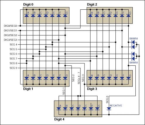
Figure 3. The MAX6958 / 59 connection to a 4-1 / 2 digit display.
BTLY Mineral Insulated Cable for Rated Voltage 0.6/1kV
1. Product Standard
GB/T12706.1, GB/T17651, GB/T18380 and BS 6387
2. Usage
This product is suitable for use in rated voltage (U0/U) 0.6/1kV system transmitting and distributing circuit.
3. Property for Use
The cable keeps good quality after firing about 180mins.(C)
The cable keeps firing 15mins, then watering and continue firing 15 min, the line keeps integrity.(W)
The cable keeps integrity after firing and mechanical vibrations 15 min.(Z)
The cable could lay whole without fitting.
The operating temperatures of mineral insulated cable core is lower than other types` cable, so the line against the loss of work, reduce energy waste. The material of cable is inorganic, that can
Reach environment requirements.
4. Type of cable
Fire Resistant Cable,Fire Proof Cable(Fire-Proof Cable) :BTTZ, BTLY, BBTRZ
Fire-Proof Cable
Fire-Proof Cable,Aluminium Alloy Casing Cable,Oxide Filled Sheath Cable,Insulated Fire Retardant Cable,Fire Resistant Cable,Fire Proof Cable
Huayuan Gaoke Cable Co.,Ltd. , https://www.bjhygkcable.com