Abstract: A single-chip microcomputer is one of the most used CPU devices, and the use of light-emitting diodes is the most commonly used device for single-chip microcomputers. This paper introduces and summarizes the working principle and the most common programming methods of LEDs, and gives a complete program.
0 Preface
Due to its small size, low price, strong function, high reliability, control and low price, the single-chip microcomputer has not only become an intelligent control tool used in the field of industrial measurement and control, but also has penetrated into every corner of people's work and life. In the engineering school, the course "Single-chip principle and application" is basically opened, and for all those who learn MCU, the most important thing is to control the LED of the LED.
1 How the light-emitting diode works
LED Light- Emitting Diode is abbreviated as LED, a diode made of a compound of gallium (Ga) and arsenic (As) or phosphorus (P). Like ordinary diodes, LEDs consist of a PN junction and also have unidirectional conductivity. When a forward voltage is applied to the light-emitting diode, holes injected from the P region into the N region and electrons injected into the P region from the N region are separated from the electrons of the N region and the P region by a few micrometers in the vicinity of the PN junction. The hole complexes, which produce the fluorescence of spontaneous radiation, and can therefore be used to make light-emitting diodes. Used as an indicator light in circuits and instruments, or as a text or digital display. The gallium arsenide diode emits red light, the gallium phosphide diode emits green light, and the silicon carbide diode emits yellow light.
The LED can only be turned on in one direction, and the reverse breakdown voltage of the LED is about 5 volts. Its forward volt-ampere characteristic curve is very steep. In use, a current limiting resistor must be connected in series to control the current through the tube to control the brightness of the LED. The current limiting resistor R can be calculated by:
R=(E-UF)/IF
Where E is the supply voltage, UF is the forward voltage drop of the LED, and IF is the general operating current of the LED.
2 LED programming method
Assume that the connection circuit diagram of the LED is shown in Figure 1. The eight red LEDs are respectively connected to the 8 pins of the P1 port of the MCU through the current limiting resistor. The MCU selects AT89C51.
2.1 Control of a single LED
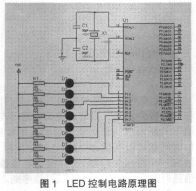
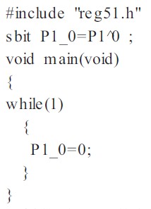
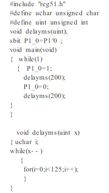
In Figure 1, as shown in the figure, if LED D1 is to be lit, since the positive pole of D1 is connected to the power supply VCC through resistor R1, then D1 must be forwarded to make the cathode of D1 low, that is, The P1.0 pin is low. This can be controlled by software. The complete C51 program is as follows:
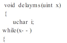
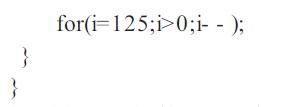
Similarly, if the LED D1 is to be blinking and blinking, the working principle is to let D1 light up and delay for a period of time, then let D1 go out and delay for a period of time and continuously cycle, so that you can observe D1 flashes and blinks. The delay can be either software delay or timing counter timing delay. This paper uses software delay. The working principle is that each instruction requires a certain clock cycle to run. A certain number of clock cycles can be used to achieve delay. Function, the crystal oscillator in this figure is 12MHz, then the 12 oscillation period is 1us, and the delay program of delay 1ms is as follows:
The control LED D1 flashes and blinks completely. The C51 program is as follows:
2.2 Control of multiple LEDs
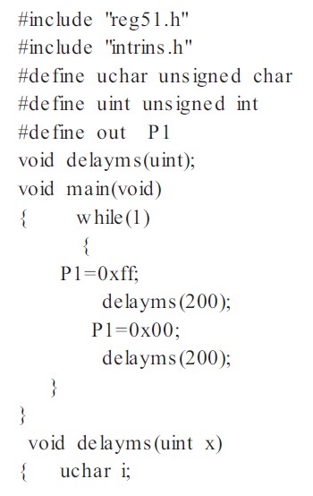
The control principle of multiple LEDs is the same as that of a single LED. In Figure 1, if you want to control the blinking of 8 LEDs at the same time, you only need to make 8 LEDs at the same time. The lighting delays for a period of time, and at the same time, the 8 LEDs are turned off and delayed for a period of time. After repeated cycles, 8 LEDs can be flashed continuously. The complete C51 program is as follows:
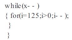
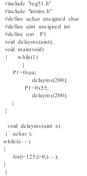
In Figure 1, if you want to control 8 LEDs D1, D3, D5, D7 odd lights and D2, D4, D6, D8 even number alternately flash, you only need to send the value of the corresponding status of 8 LEDs connected to P1 port. This function can be implemented with the P1 port and delay. The complete procedure is as follows:
2.3 Control of the flow lamp
For the pattern water light, the working principle is the same as that of the previous multiple LEDs. It only needs to send the value of the corresponding port of the lamp in different states to the corresponding control port and delay it for a certain period of time. Therefore, the port value of the corresponding state is stored in an array, and the value of the array is taken cyclically, and each time a value is delayed for a period of time, that is, the program is omitted.
3 Summary
MCU is used more and more in various industries. The paper summarizes the use and programming methods of LEDs in MCU, and gives the working principle and complete program of various methods.
PVC insulated wires are coated with pvc to prevent from electric shock. Its light weight reduces manual handling difficulties. This wire consists of copper/aluminum conductor, insulated with moisture and heat resistant, chemically cross-linked polyethylene insulation. PVC does not conduct electricity and is therefore an excellent material to use for electrical applications such as insulation sheathing for cables. With fine design and high quality, the wire boasts of large electricity transmission capacity. The maximum continuous operating temperature for general type is 75℃. But the special type BV-105 can work well at the temperature of 105℃.
Standard:
GB/T5023-2008, JB/T 8734-2016

Rated Voltage:
450/750V

Application:
cables are extensively used for domestic home appliances wiring, house wiring and internal wiring for lighting circuits in factories, power supply for office automation, in control, instrumentation, submarine, mining, ship wiring applications etc. due to its high tensile strength, superior conductivity, better flexibility and ease of jointing.


Advantages:
- A non-hygroscopic insulation almost unaffected by moisture.
- Non-migration of compound permitting vertical installation.
- A tough and resilient sheath with excellent fire retarding quality.
- High current and short circuit current rating.
- Not affected by vibration.
- Reduce internal stress and low dielectric loss
- Complete protection against most forms of electrolytic and chemical corrosion.
- Good ageing characteristics
- Easy installation
Welcome to visit our factory to learn more about us. If you have any questions, please feel free to contact us.
PVC Insulated Wire,Heat Resistant PVC Insulated Wires,PVC Insulator Sheath Electrical Wires,Flexible PVC Electrical Wires
Fujian Lien Technology Co.,Ltd , http://www.liencable.com