0 Preface
This article refers to the address: http://
A smart car, also known as a wheeled robot, is a comprehensive system that combines sensors, computers, automation, communications, and machinery. In the design and production process of smart cars, control algorithm debugging is an extremely important and critical link, facing many urgent problems: whether the smart car can run according to the pre-designed ideas; whether the control strategy meets the actual needs; What are the real-time parameters of the smart car when there is a problem? In response to these problems, many scholars have proposed simulation-based solutions. Some scholars have proposed a geometric model of mechanical system based on parameterization, and used Lagrangian method to establish the system dynamics equation to analyze the dynamics of the virtual mechanical system. However, due to the complexity of the mechanical structure of the vehicle, this modeling and simulation method is too cumbersome, which affects the efficiency of simulation and research. Tsinghua University's PlaSTid simulation platform developed for the national college student smart car competition, although its dynamic model is relatively simple, but the model is an idealized model, and there are few considerations for some parameters affecting the running status of the smart car, such as the car and There are some differences between the simulation results and the actual friction coefficient between the road surface and the mechanical properties of the car. Some scholars have proposed a smart car hardware-in-the-loop simulation system that exploits the strengths of the hardware in the ring. However, the software is still based on the virtual simulation platform LabVIEW. The analysis and decision of the control algorithm runs on the host computer, which is out of the software running environment of the vehicle model entity. The simulation results are also different from the actual ones, so its application has considerable limitations. Sex.
The author designed a real-time monitoring system for the running status of smart cars based on wireless communication technology. The system takes the car model as the experimental subject, and the vehicle controller completes the data collection, analysis and decision making of the smart car. The upper computer obtains various operating parameters of the vehicle model through wireless communication technology, and monitors the running state of the vehicle model.
1 overall system design
1.1 Zigbee technical analysis
Zigbee technology is a short-range, low-power, low-cost two-way wireless communication technology [5-6], the working frequency band is 2.4 GHz for the global common frequency band, and the data transmission rate is 10~250 kbit/s, without license. The Zigbee protocol consists of an application layer, a network layer, a data link layer, and a physical layer, wherein the physical layer and the link layer follow the IEEE 802.15.4 protocol. A Zigbee network supports 255 devices; it uses advanced AES128 encryption algorithm to provide data integrity check; it has carrier sense multiple access, collision detection (CSMA/CA) mode, and has good compatibility. Zigbee defines three types of node devices, namely a coordinator, a routing device (FFD), and a terminal device (RFD).
The Zigbee network consists of these three devices, but must include one coordinator and only one coordinator. The coordinator is the center of the entire network. It is responsible for the formation of the network, the management of the network nodes, the storage of network node information, the search for routing messages between nodes, and the continuous reception of information. The routing device also acts as a coordinator, responsible for other routers or terminal devices to access the network and expand the network scope; the terminal device is a unit that implements specific functions [7]. The Zigbee network can implement a variety of star, tree, and mesh types. Topology.
The company's IP-Link product is a wireless communication module that integrates RF transceiver, microprocessor and multi-topology network functions.
The IP-Link1200 module includes an AVR microprocessor that complies with the IEEE 802.15.4 protocol's 2.4 GHz license-free ISM band RF transceiver, which can be configured into any network topology. Therefore, IP-Link1200 is a wireless communication module that fully meets the requirements of smart car measurement and control systems.
1.2 The structure of the monitoring system
In order to enable on-line monitoring of the operating status of multiple smart cars, the system uses a star topology. The network node of the system is divided into a coordinator node and a terminal node, wherein the coordinator is connected to the host computer, and the terminal node is embedded in the smart car.
The upper computer (ie, the PC) and the lower computer (smart car) use wireless communication. The lower computer collects the driving speed and road condition information of the smart car, determines the driving direction of the smart car, and calculates the action data of the next step. At the same time, the lower computer sends the collected data and the next action data to the upper computer, so that the debugger can observe the current driving parameters of the trolley and the corresponding driving state of the trolley on the upper computer. Therefore, the communication mode between the upper computer and the lower computer is that the upper computer first sends a communication command to the lower computer, and then receives the running state information of the trolley transmitted by the lower computer. The host computer saves, displays, and corrects the information, and sends the corrected parameters to the lower computer.
2 system hardware design
The smart car is dominated by the MC9S12XS128 MCU, which has abundant internal resources. The pulse width modulation module of the single-chip microcomputer is used to drive the steering gear and the motor of the smart car. Two PWM channels are used as the steering angle control, and one PWM channel is used for the motor speed control. The capture timing function and A/D conversion of the single-chip microcomputer are utilized. The module collects road signals.
The connection between the MCU and the IP-Link1200 is simple and convenient. The RXD of IP-Link1200 can be directly connected to the TXD of the SCI serial port of the MCU. The TXD is connected to the RXD of the serial port of the MCU, the RESET terminal is connected to the PE1 port of the MCU, and the IP-Link1200 is initialized by PE1, that is, through the PE1. A negative pulse of 10 ms is output. The circuit diagram of the lower computer is shown in Figure 1. 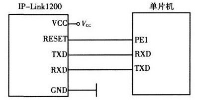
Figure 1 lower computer circuit diagram
When the IP-Link1200 is connected to a PC, it must be level-shifted to convert the TTL level to the RS-232C level. This conversion can be done with a single MAX232 chip. The RESET terminal of the IP-Link 1200 is connected to a reset circuit that resets the IP-Link 1200 at power-on or resets the IP-Link 1200 by pressing the RST button. The circuit diagram of the host computer is shown in Figure 2. 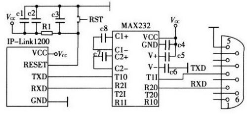
Figure 2 upper computer circuit diagram
3 system software design
3.1 Communication Protocol
In this system, full-duplex communication is used between the upper computer and the smart car. Wireless networks use a star network topology. The IP-Link 1200 connected to the host computer is the coordinator node, and the IP-Link 1200 connected to each smart car is the terminal node. The node number of each terminal node in the wireless network is the identification number of the smart car.
The definition of the communication protocol ensures the correct rate of sending and receiving data. Experiments show that the probability of two AAHs followed by one 55H appearing in the data is small. Therefore, two AAHs followed by one 55H are used as the starting markers of one packet. When sending data, the start flag is added before the packet. When the receiver receives 1 data packet, it first checks whether the first 3 digits are the start flag, and if so, continues to receive the data packet; otherwise, it abandons the reception. The command code is the command sent by the host computer to the lower computer, which takes up 1 byte. The lower 4 bits are the operation code. The "0" indicates that the upper computer needs to read the data in the lower computer; the "1" indicates that the upper computer needs the lower position. Write data to the machine. The upper 4 bits are the instruction code, which indicates which group of data of the bit machine needs to be read/written, such as servo parameters, road condition parameters, speed parameters, etc. The data length bit indicates the number of data in the packet. The error correction processing of the data adopts the CRC check method.
3.2 Communication module design
The software of the communication system mainly has two parts. One is that the upper computer receives and transmits data from the serial port, and the other is that the smart car receives and transmits data from the IP-Link 1200 under the control of the MC9S12XS128 single chip microcomputer. The communication subroutine sets the baud rate of the serial port to 38 400 baud at system startup, and sends control messages to each sub-node in the communication network through IP-Link 1200 to check whether each node is connected properly. The communication subroutine in the smart car sets the baud rate of the serial port to 38 400 baud at power-on. The node number of each terminal node in the wireless network is set to the identification number of the smart car, and the network topology of the IP-Link 1200 is set to The star type, transmission baud rate is 38 400 baud, channel is 11, and so on. The establishment of the Zigbee network is initiated by a coordinator connected to the host computer. First, the coordinator performs a scan search, finds an unused best channel to establish the network, and then scans the search to find new terminal nodes to join the network.
3.3 lower computer software design
In the communication between the upper computer and the upper computer, the upper computer is in an active position, and the lower computer is in a subordinate position. When the lower computer does not receive the communication command from the upper computer, the trolley continuously collects the road information in front, extracts the guide line, collects the traveling speed of the trolley, generates control parameters, and controls the trolley to advance along the guide line. When the car receives the communication command from the host computer, it first determines the type of the command. If it is the correction data packet sent by the upper computer to the lower computer, the lower computer receives the data and modifies the operation parameters; if the upper computer requests the lower computer to transmit the instruction of the trolley operation parameter, the lower computer immediately packs and uploads the transmission type word.
3.4 PC software design
The PC software is written in VB language. The Windows-based windowing program design MFC makes the human-machine interface vivid and intuitive, and easy to operate.
The main function completed by the host computer is responsible for the initiation of a communication, selecting the parameter group to be collected, storing and displaying the received data, and correcting the parameters. Its functional modules are divided into main control module, communication module and database management module. The main control module is composed of a data receiving sub-module, a display sub-module and a parameter correction sub-module. The data receiving sub-module is composed of an image information sub-item, a steering gear related parameter sub-item and a PID parameter sub-item; the parameter correcting sub-module completes the correction of the steering gear corner parameter and the PID algorithm, and when the parameter correction is completed, the data transmission is performed immediately. The parameter correction command is used to modify the corresponding parameters of the lower computer.
4 Experiment and analysis
By applying the system to debug the smart car, the parameters of the smart car operation can be obtained in time, and the running state of the smart car under the given parameter control can be observed in time. At the same time, by modifying the corresponding parameters, the operating state of the smart car is adjusted to achieve the optimal state of operation of the smart car.
Figure 3 shows the parameters of the motor control during the operation of the smart car. On the host computer, it is possible to observe the influence of the changes of the PID factors on the running state of the smart car when the smart car is running in the same section. By continuously adjusting the various factors, the running state of the smart car in the same road section is optimized. 
Figure 3 Parameters of motor control during smart car operation
5 Conclusion
This paper applies Zigbee wireless communication module to design and realize the real-time monitoring system of smart car running status. The system can timely obtain the parameters of the smart car during operation, and observe the influence of the parameter changes on the running state of the smart car in time, so that the debugging of the smart car is no longer blind, but is targeted. At the same time, it also provides an effective basis for offline improvement of control algorithms.
PLC splitter is a type of optical power management device that is fabricated using silica optical waveguide technology. It features small size, high reliability, wide operating wavelength range and good channel-to channel uniformity, and is widely used in PON networks to realize optical signal power splitting.
Bwinners provides whole series of 1×N and 2×N splitter products that are tailored for specific applications. All products meet GR-1209-CORE and GR-1221-CORE requirements. fiber optic splitter plc, fiber optic cable splitter, optical splitter , Mini Type PLC Splitter , Cassette Type PLC Splitter, Insertion Module PLC are available.
Features:
Low insertion loss and low PDL
Various coupling ratio
Environment stable
Single mode and multimode available
High Reliability and Stability
High Channel counts
Wide wavelength range
Customized packaging and configuration
Applications:
FTTx Construction
Fiber Optical communication system
Fiber Optical access networks
Fiber Sensor
Fiber CATV networks
Local area networks
Cassette Fiber Plc Splitter,Gpon Splitter Cassette,Plc Splitter Cassette Box,Optical Splitter Cassette Type
Sijee Optical Communication Technology Co.,Ltd , https://www.sijee-optical.com