As a test engineer, we have to deal with complex tests before the assembly of the Electronic Control Unit (ECU). In this essay, I will try to make you more aware of the various applications and testing strategies. I hope to help you sort out the ideas so that you can ask system integrators and/or ATE suppliers more accurately and help you make the right choice.
This article refers to the address: http://

product development
Of course, all newly designed products are validated and tested before they are released. HILs (Hardware In the Loop) are increasingly important in laboratory testing strategies. In general, this is mainly used to test the response of the ECU in the event of an external fault, including: loss of signal, short circuit to ground or Vbat, or erroneous data. In the ATE industry, the fault insertion switching system is usually selected to implement this test. Several companies offer the hardware devices that I have mentioned above for fault generation/injection. Because the safety of ECUs in automobiles is critical, such high-level tests are equally important.
Process test
In the process of assembly and quality testing, the automotive industry appears to be somewhat conservative in the introduction of new technologies. According to INEMI's report, the automotive industry lags behind other industries in introducing small-size packages of PCBs. The main influencing factor is the use environment - temperature range -40 ~ +250 degrees Celsius (exhaust gas sensor operating temperature up to 580 degrees Celsius), multi-G vibration requires structural design standards far higher than the general industry, such as home computers. The original device density is also much lower than other consumer products. In addition, in the future, most of the clocks on the car will not exceed 150MHz, and the test points are still mechanically and electrically accessible. This information indicates that ICT testing (In-circuit testing) will still occupy an important position on the assembly line in the next few years.
For the sake of quality and reliability, AXI (Automatic X-Ray Inspection) is also highly valued as part of the testing strategy. Because the BGA package has a large number of device pins, it is important to verify that all pins are soldered firmly, especially for those safety-related ECUs such as ABS anti-lock systems, airbag controllers, active safety systems and lines. Transmission control (X by Wire) and so on. Because the car's steering and braking (coming soon) are fully electronically controlled, these tests will be critical in the near future.
Because optical inspection does not see the underlying portion of the BGA chip, and in fact not all I/O have terminals, AXI is increasingly important in testing strategies. Despite the economic downturn in 2008 and 2009, the number of newly purchased cars in the world is still as high as 50 million.

Current AXI systems have very low detection speeds (3D X-ray inspection is about 0.6 square inches per second and 2D X-ray inspection is about 6 square inches per second). If the detection speed is increased, the ATE manufacturer will also increase the analysis speed of the equipment accordingly, and the resulting cost increase is also an important consideration in the cost-sensitive automotive industry. In many cases, it is possible to perform partial X-ray inspection of the ECU and AOI or ICT detection for other parts to ensure the efficiency of the production line.
Various types of needs
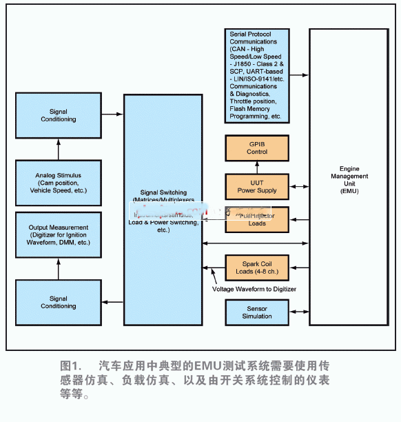
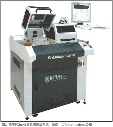
The complexity of EOL determines the difficulty of testing, because the task here is to simulate the real working environment, so completing these complex tests requires a well-planned plan. There are some requirements for ECUs to consider in functional test systems. include:
Power requirements: The electronic control unit determines when to drive electromechanical devices such as motors and coils. According to the current 12V standard for automotive power buses, this means that large currents can occur – up to 100A for electric power steering! Variable valve actuators on V8 engines require up to 2400W of peak power! Equivalent to a current peak of up to 200A at 12V! So proper switching specifications and cooling capacity are important.
Hybrid cars: Power system cigarettes can be as high as 300V, but most peripherals—such as lights, entertainment, and in-vehicle equipment—run at very low voltages. So there is usually a voltage conversion in this type of design. And because the voltage of 300 VDC is dangerous, isolation tests must be considered in the test plan to ensure safety.
Serial communication: The automotive industry has embraced the concept of networking, or in their own terms, "multiple connections" - in accordance with the connection structure of the various ECUs in the car. Multi-channel technology has been used to display diagnostics, security and performance information, and is now also used for entertainment and navigation. However, the fact that too many protocols are actually used is a problem.
Some organizations such as AUTOSAR (Automotive Open System Architecture) are looking for ways to simplify ECU development and interconnect communication, but it takes time to implement. So now whether you are buying or building a test system, you have to deal with a variety of different protocols.
RF applications: AM/FM broadcasting in automotive ECU testing, RF and microwave testing has been applied more widely. The Bluetooth interface interconnected with mobile phones has been widely used in low-cost cars. IEEE has reported the use of BAP (Bluetooth Access Points) to establish a conceptual design of a micro network. The goal of this design is to avoid conflicts in device identification. Finally, there is interactive cruise control that uses the radar band (40 GHz) to maintain a safe distance.
As printed circuit board technology has continued to evolve, it has paved the way for the creation of a host of exciting product innovations. A prime example is the development of the PCB for LED lighting. The LED is soldered to the circuit board and features a chip that produces the light when electrically connected. A thermal heat sink and a ceramic base are used to bond the chip.
An LED PCB Board tends to generate a high volume of heat, making it difficult to cool via traditional means. Consequently, metal core PCBs are frequently chosen for LED application due to their enhanced ability to dissipate heat. Aluminum in particular is often used to manufacture circuit boards for LED lights. The Aluminum PCB typically includes a thin layer of thermally conductive dielectric material that can transfer and dissipate the heat with much greater efficiency than a traditional rigid PCB.
PCB = printed circuit board and PCBA = printed circuit board assembly. For PCB, it means the copper circuits be printed on a board, and so the main composition of PCB are copper and board.
The copper is the circuits material and the circuits designed by the PCB designers. Depends on the current in the circuits, the PCB copper thickness could be done with 0.5oz-10oz. But the PCB designers need be noted that the copper track width/space need be enlarged with the thickness. For example, the minimum copper track width/space could be 3mil/3mil with 0.5oz, but would be 4mil/4mil with 1oz.
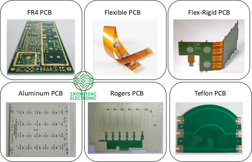
The PCB board could be rigid PCB, could be flex PCB and also could be Flex-Rigid PCB. And the materials could be FR4, PI, Aluminum, Copper-based, Rogers, Teflon, etc. They have different applications. For example, FR4 PCB is the most commonly used for rigid PCB and almost good for all electronics products; PI is the most commonly used for flex PCB; Aluminum and copper-based have good thermal diffusivity and always used for LED PCB ; Rogers PCB and Teflon PCB are always used for High Frequency PCB, etc.
We are the one-stop shop for all kinds of PCB manufacture service from PCB Prototype to big volume, which could save our customers a lot of time and money.
PCB Manufacture Capabilities
|
Features |
Capabilities |
|
Layers |
1-36 layers |
|
Material |
FR-4, Aluminum, Copper, Polyimide, high frequency (Rogers, PTEE, PI), etc. |
|
PCB Type |
FR-4 Standard PCB , Aluminum PCB, Copper-based PCB, HDI PCB , Rigid-Flex PCB, Flex PCB, Thick Copper PCB and Rogers PCB, etc. |
|
Board Thickness |
0.1mm-6.0mm |
|
Copper Thickness |
1/2oz-6oz(18um-210um) |
|
Biggest Board size |
600mm*1200mm |
|
Min Tracing/Spacing |
0.075mm/0.075mm (3mil/3mil) |
|
Min drilling Hole diameter |
0.15mm(6mil), 0.1mm(4mil)-laser drill |
|
Solder Mask |
Green, Black, White, Red, Yellow, Blue and Purple, etc. |
|
Silkscreen color |
White, Blue, Black, Red, Yellow |
|
Surface finish |
HASL Lead free, Immersion Gold (ENIG), Immersion Tin, Immersion Silver, OSP, Carbon oil, etc. |
|
Special Techniques |
Impedance Control, Gold Fingers, Blind/Buried vias, Peelable solder mask, Half holes, Via-in-Pad and Countersink hole, etc. |
PCB Products Show

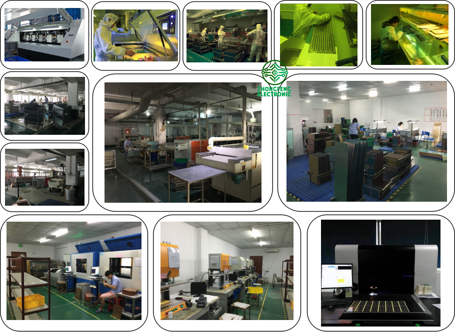
PCB Factory Show

LED PCB
LED PCB,LED PCB Board,Aluminum LED PCB Assembly,LED PCB Strip
ZhongFeng Electronic Technology Co., Limited , https://www.dopcba.com