introduction
The tablet market is expected to grow from 50 million units in 2011 to more than 200 million units in 2016. But despite this, there is no standard tablet architecture so far. Some tablets are powered by a single lithium battery, while others use two lithium batteries. No matter how many lithium batteries are used, all tablet manufacturers want to maximize battery life. In addition, the backlight of the display is one of the most power-hungry systems in tablets. In the recently released tablet, the number of backlight LEDs ranges from 20 to 36. This article will guide readers on how to choose the best WLED driver and LED string configuration to meet tablet application requirements without sacrificing efficiency and battery life.
Tablet backlight requirements
Like laptops or netbooks, tablet backlight driver applications are also based on DC/DC converters and grounding resistor paths for LEDs. Such applications generally have the following requirements:
1. Low EMI in the RF range
2. No visible flicker during brightness height
3, ceramic output capacitor piezoelectric hum is caused by the smallest audible noise
4, the display brightness is consistent
5, high dimming ratio
6, the highest efficiency, the implementation of maximum battery life
It is relatively easy to meet the first requirement, ie low EMI in the RF range. Power designers have been working hard to achieve this goal for years, and they have tried many methods, such as setting the switching frequency and concurrent harmonics outside the RF range, using shielded inductors, and designing the PCB to the minimum length where appropriate. But use a wider wire, and so on. Some driver ICs have integrated MOSFET gate drive circuits with tiered rise times to reduce noise in the RF range.
The type of brightness adjustment greatly affects the next four requirements. When using Pulse Width Modulation (PWM) dimming, the LED current is pulsed on and off at its maximum current level during regulation to produce an average DC LED current. At this time, as long as the PWM brightness adjustment frequency is much higher than 60 Hz, the backlight flicker is not so obvious. If analog brightness adjustment is used, flicker is not a problem because the LED DC current level drops below its maximum value during brightness adjustment.
The third requirement, the audible noise of ceramic capacitors, is minimal, depending on the topology of the drive. Figure 1 shows a simple driver with its current sense resistor as the ground path for the LED current. The converter regulates the voltage of the current sense resistor to control the LED current.
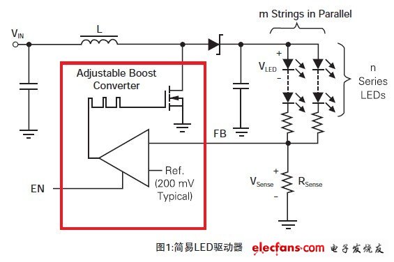
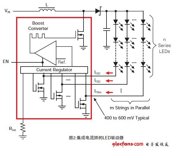
Figure 2 shows the driver for the integrated current sink. The driver samples the voltage of each current sink to ensure that the converter provides just enough power to keep the current sink operating.
As with flicker, there is no problem with analog dimming because the output capacitor voltage has only a small change to accommodate small changes in LED current. However, if PWM brightness adjustment is used, the way the driver prevents the output capacitor from discharging becomes important. The simplest driver also has a resistor between the driver feedback (FB) pin and ground. When the converter's converter is effectively turned off, the output capacitor begins to discharge sharply at low brightness adjustment duty cycle. Some of the more complex drivers integrate a current sink (shown in Figure 2) that can replace current sense resistors. They simply turn on the absorber and the DC/DC converter that powers the LED, removing the discharge and recharge paths of the output capacitor.
The fourth requirement, consistent display brightness, is perfectly achieved by precisely matching the LED currents of all strings. A key feature of integrated current sink drivers is the extremely precise matching between strings. For some drivers without integrated current sinks, ballast resistors placed in series with the LEDs improve the match between the strings.
The fifth requirement, the high brightness adjustment ratio (for example: 0.1%, or 1000:1), is difficult to implement with a simple driver, whether using analog or PWM regulation. When using analog dimming at low duty cycles, the analog control voltage becomes so low that the IC's leakage current and compensation voltage can greatly reduce accuracy. PWM dimming using a simple driver is the most common implementation, implemented by a fully switching converter. This brightness adjustment produces a soft-start time for the converter, forcing the PWM dimming frequency to become very low, close to the flicker range. The duty cycle causes the output capacitor to discharge and hum during recharging. Therefore, with the integrated current sink, the high brightness adjustment ratio can be perfectly achieved because it can be switched very quickly.
The sixth and last requirement, high efficiency, is not only related to the drive, but also to the LED configuration. The power MOSFET, inductor, and rectifier diode of the driver DC/DC converter together determine the efficiency of the converter. The ground path of a simple driver is a current sense resistor. The lower the FB voltage of the converter, the higher the overall drive efficiency. Similarly, for an integrated current sink driver, the lower the minimum operating voltage of these absorbers, the higher the efficiency of the driver. Simple drivers are almost always more efficient than drivers with current sinks, assuming that they have identical internal components because current sinks typically require higher bias voltages than current sense resistors. However, to meet the other performance requirements of tablets, drivers with integrated current sinks are generally the best choice.
Best LED configuration
Minimizing power consumption and maximizing battery life by selecting the optimal number of strings and the optimal number of LEDs per string is a challenging task. Using fewer strings requires more LEDs per string and can result in a higher output voltage of the boost converter. The greater the difference between the input and output voltages of the boost converter, the lower its efficiency. In addition, more strings result in higher total output current, as well as higher inductance and boost rectifier diode losses. Using more strings allows fewer LEDs per string and provides a lower output voltage, but it requires more current sinks and has to consume more power, reducing the overall efficiency of the drive.
The 20 LEDs use 5 LEDs in series for one string and 4 strings in parallel (5S4P) configuration. 24 LEDs use 6S4P configuration, while 36 LEDs use 6S6P configuration, the best simulation efficiency occurs. Based on these results, the rule of thumb for maximizing the efficiency of tablet backlight drivers is to choose the number of S and P that are equal or as close as possible to each other, but the number of P should be smaller in the case of only two options.
Example backlight configuration
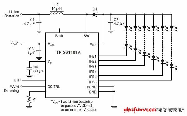
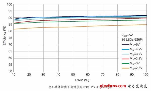
According to the previous analysis, backlight drivers with integrated current sinks, such as the Texas Instruments TPS61181A notebook backlight driver, can be optimized for tablet backlighting (see Figure 3). For tablets that use two lithium-ion batteries, both the driver and boost power stages can be powered directly from the battery. For tablets that use only a single-cell Li-Ion battery, the driver bias rail can be powered by the panel's AVDD rail or another system power supply (4.5V or higher). Since the TPS61181A can provide slightly higher power than most tablets require (that is, the power FET is slightly too large, the RDS(on) is very low), so the conversion is designed for this output power. This converter further reduces power consumption, further maximizing efficiency. Figure 4 shows the measured efficiency results for the 6S6P configuration TPS61161A.
in conclusion
Choosing the best backlight driver for your tablet requires consideration of all application requirements. The integrated current sink driver is then the best choice for all requirements except efficiency. However, carefully choose a driver with a slightly larger converter, the lowest power-down external components, and the best LED string configuration, which can bring a tablet that maximizes battery life while meeting all design requirements. Backlighting.
We disign and manufacture Linear Actuators For Smart Furniture, modern furniture, like: shelves, bookshelves, shelving, chairs, tables, and desks for the home and office.
Pls feel free to contact us for more details about this product or other optional product or customize your product!
Smart home furmiture Linear Actuator, a Electric Linear Actuator with easy opeation, simple installaion, light weight and compact structure, this Actuator is widely used in different fields, specialized for smart home furniture, such as electric sofa, TV lift, leisure sofa, recliner chairparts, electric bed, door opener, cabinet door, pool & spa lift etc.
Actuators For Smart Furniture
Electric Linear Actuators, Smart Furniture, Smart Recliner, Smart Bed
TOMUU (DONGGUAN) ACTUATOR TECHNOLOGY CO., LTD. , http://www.tomuu.com