introduction
This article refers to the address: http://
At present, the reversing device commonly used in China is an ultrasonic reversing radar. Although this device can accurately measure the distance between the tail and the obstacle behind the vehicle, the driver cannot judge the exact position of the obstacle due to the visual blind zone, and can not perceive the pit. Or low obstacles. The research trend at home and abroad is based on the reversing radar, using digital image processing technology, using a powerful embedded processor to develop a vehicle-mounted visual reversing device that combines the advantages of detecting the rear object distance and monitoring the rear image. These new devices are more expensive and are currently only used in mid- to high-end cars. To this end, a vehicle-mounted visual reversing device based on Intel PXA270 hardware platform and embedded WindowsCE operating system is proposed.
1 system structure
The hardware circuit block diagram of the visual reversing device proposed in this paper is shown in Figure 1. It is mainly composed of Intel embedded processor PXA270, video acquisition, ultrasonic ranging and other circuits. Two pairs of ultrasonic transducers, signal conditioning circuits and microcontrollers complete the distance measurement of the obstacles and send them to the main system in the vehicle through the LIN bus; the video composite signals collected by the camera are sent to the video decoding chip through the coaxial cable. A/D conversion, and generate video signal input in YUV422 format. PXA270's fast capture camera interface; the main system processor uses character overlay technology to play image signals containing parameters such as obstacle distance on the TFTLCD screen.
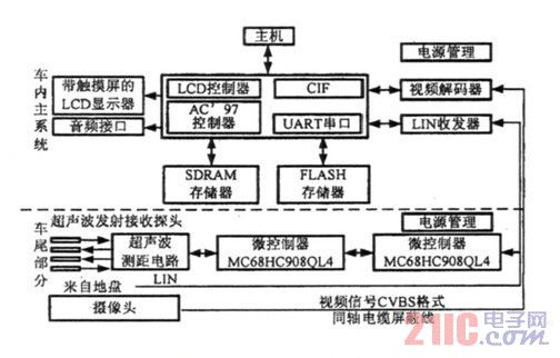
Figure 1 Visual reversing hardware circuit diagram
1.1 Embedded Processor PXA270
The embedded processor PXA270 used in this system has a maximum frequency of 624MHz, and incorporates WirelessMMXTM technology to enhance multimedia processing capabilities. It also incorporates IntelSpeedStep dynamic power management technology to maximize CPU performance. Reduce mobile device power consumption; and have a wealth of external interfaces: such as AC'97 controller, LCD controller, CIF interface, SD card interface.
1.2 Video acquisition circuit
The CIF interface of the in-vehicle main processor PXA270 can only process digital signals, so the analog signals collected by the camera must be converted first. The video input decoding module of the system is constructed by TI's video decoding chip TVP5150 and peripheral circuits. Its main function is to send the standard PAL TV analog signal collected by each CCD camera to the video decoder to complete the clamping of the video image. Pre-processing such as anti-aliasing filtering, analog video signal to digital YUV4: 2:2 conversion and separation of signals such as luminance/chroma and horizontal/vertical synchronization. The decoder chip and the PXA270 are connected through the CIF interface. The PXA270 accesses the internal registers of the TVP5150 through the I2C bus, coordinating the working communication between the processor and the decoder.
1.3 Ultrasonic distance measuring circuit
The ranging circuit is mainly composed of an ultrasonic transmitting circuit and a receiving circuit, and the principle block diagram is shown in FIG. 2 . The module MCU uses Freescale's MC68HC908QL4, which has high reliability and strong anti-interference ability. It contains 4kB flash memory, four-channel 10-bit A/D converter, and integrated LIN controller. The ultrasonic waves detect the distance between the objects and transmit the data to the in-vehicle main processor via the LIN bus. Since the ultrasonic distance measurement only provides the driver with the information after the vehicle is reversed, the vehicle speed is slower when reversing, and can be considered as static compared with the sound speed. Therefore, the pulse ranging method is used to measure only the ultrasonic wave between the measuring point and the target. The round trip time calculates the distance is simpler.
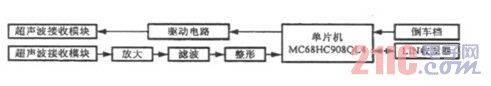
Figure 2 schematic diagram of ultrasonic ranging
(1) Ultrasonic transmitting circuit The ultrasonic transmitting circuit is shown in Fig. 3. When the driver's handle of the car is turned to the reverse gear, the distance measuring circuit starts to work, and the microcontroller emits a 40 kHz square wave signal, which is amplified by the driving circuit and transmitted through the probe, and the counter starts counting.
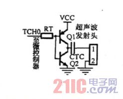
Figure 3 Ultrasonic transmitting circuit diagram
(2) Ultrasonic receiving circuit The ultrasonic receiving circuit is shown in Fig. 4. The dedicated preamplifier CX20106 is composed of a preamplifier, a limiting amplifier, a bandpass filter, a detector, an integrator, and an integer circuit. Among them, the preamplifier has an automatic gain control function. The ultrasonic signal is reflected in the air and then reflected by the obstacle. The echo is received by the receiving probe and converted into an electrical signal. After the cable is connected to the external interrupt port of the microcontroller, the counter stops counting and the obstacle is calculated. distance.
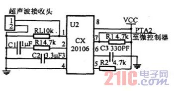
Figure 4 ultrasonic receiving circuit
1.4 LIN bus transceiver interface circuit design
LIN is a low-cost serial communication network for distributed electronic system control in automobiles. It is an auxiliary bus network that provides significant cost savings without the bandwidth and speed of the CAN bus. LIN communication is a data format based on SCI asynchronous serial communication. It adopts single master/multi-slave mode and uses only one 12V signal bus and one node synchronous clock line without fixed time reference. TJA1020 is a common physical interface chip of LIN master/slave protocol controller and LIN bus. The interface circuit is shown in Figure 5.
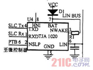
Figure 5 LIN transceiver interface circuit
2 software design
2.1 Customization of the system platform
Windows CE is an efficient, scalable operating system designed specifically for a variety of embedded systems and is widely used in a variety of embedded products. In order to customize the WindowsCE operating system of the device, firstly, according to the hardware configuration, the BSP board-level support package provided by Intel is imported in the PlatformBuilder development environment, and the OEM hardware adaptation layer and components are developed. After the operating system image is successfully established, the platform is transferred to the target device for testing. Finally, the software development kit is exported to develop the application in the EVC++ environment. The WindowsCE customization process is shown in Figure 6.
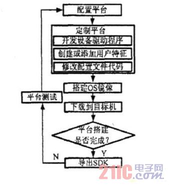
Figure 6 Customization process of Windows CE operating system
2.2 camera driver design
The driver described in this article is implemented under WindowsCE. The main task of the camera driver is to control the flow of video data in the hardware and provide a standard interface for the camera application. In order to simplify the programming difficulty, considering that the working mode of the CIF interface is relatively independent, a single-chip driver model driven by the stream interface is adopted: that is, an entry point dynamic link library containing the driver is created for each stream interface driver, and the file I is implemented. The /O and power management functions are handed over to the kernel. The flowchart of the camera driver is shown in Figure 7, and its work is as follows:
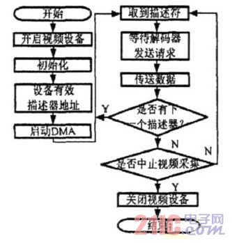
Figure 7 camera video data transmission flow chart
(1) Responsible for querying the information of the camera decoder through the I2C bus, and adjusting the settings of the camera decoder;
(2) Establish and control the DMA transmission channel, and transfer the data information in the three FIFOs in the CIF interface to the memory through DMA, thereby realizing fast and high-quality data transmission;
(3) Provide an interface that can be used by the application.
2.3 Ultrasonic ranging software design
The ultrasonic ranging software mainly includes ranging and data transmission, and its flowchart is shown in FIG. 8.
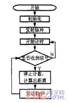
Figure 8 Ultrasonic ranging flowchart
3 Conclusion
After the joint debugging of the software and hardware was successful, the reverse test was carried out on the actual vehicle. The video signal actually captured by the camera is displayed on the LCD as shown in FIG. The numbers in Figure 9 are ultrasonic ranging data. Tests show that the system is reliable and can not only display the rear panoramic view in real time, but also accurately measure the distance between the car and the obstacle behind the vehicle, which basically meets the design requirements.
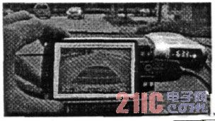
Figure 9 Video capture window of the visual reversing device on the LCD
Wireless Smartphone Charger,Wireless Charger,Android Wireless Charger,Apple Iphone Wireless Charger
Dongguan baiyou electronic co.,ltd , https://www.dgbaiyou.com