As the latest interface standard, USB type-c? There has been a lot of attention in the computing and consumer electronics markets. Combining functions with satisfying consumer demands, USB type-c is promising to be one of the most popular interfaces, but it may also be the most troublesome interface for people. A large number of terms such as Alternate Mode (Alt Mode), Accessory Mode, Structured VDM, and Unstructured VDM make consumers and technicians puzzled. These terms define how the USB type-c interface supports a variety of non-USB functions. This article will provide readers with an analysis of all non-USB features supported by the USB type-c interface, the components that system engineers will use, and the features consumers need to know. This article also discusses video mode, data mode, audio mode, debug mode, and high power mode.
This article will give you a brief introduction to USB Type-C. It has five key features that make the USB Type-C a flexible, scalable interface.
powered by
The default 5V power supply for the USB Type-C interface is backward compatible with the previous USB interface. Not only that, the new USB Type-C interface consists of four pins dedicated to power and ground. "USB Power Delivery SpecificaTIon" allows the USB Type-C interface to support up to 20V and 5A.
Symmetrical connection
The USB Type-C interface is symmetrical, so its plugging and unplugging and cable orientation are both positive and negative. The liberation of the plug-in direction solves the main troubles brought by the previous interface. The type of the previous interface indicates the function of the attached device (Type-A interface is used for the host and Type-B interface is used for the external device). The USB Type-C interface can access either end, and the functionality is defined by the hardware being accessed. The connectors on both ends of the USB Type-C cable are the same, so the plugging and unplugging of the cable is simplified.
bandwidth
USB Type-C supports USB 2.0, USB 3.1 Gen 1 (SuperSpeed ​​USB 5Gbps) and USB 3.1 Gen 2 (SuperSpeed ​​USB 10Gbps) data rates. USB 2.0 and USB 3.1 are defined by separate specifications. SuperSpeed ​​USB differential signal pairs are assigned on both sides of the interface, so a set of SuperSpeed ​​USB signal transmission connections is used when inserting the interface in either direction.
Channel configuration
The USB Type-C interface contains two channel configuration (Channel ConfiguraTIon) signal pins (CC1 & CC2) for function negotiation. The above signals determine the direction in which the interface is inserted and are used to negotiate the power, alternate, and peripheral modes on the interface.
Non-USB signal transmission
The USB Type-C interface supports a variety of OEM product customization modes to extend device functionality. Figure 1 shows the pinout of the USB Type-C. Some pins can be reassigned based on the product type. The pins in the yellow-marked portion can be reconfigured with a full-featured USB Type-C cable. Not only that, but the pins in the orange label section can also be reconfigured for Direct Connect ApplicaTIon.
Signal redistribution is achieved through negotiation on the CC channel. The interface can enter two modes, peripheral mode and alternate mode. To enter peripheral mode, a simple logic check is performed on the CC channel to determine which peripheral mode is required. To enter the alternate mode, Biphase Mark Code (BMC) is used on the CC channel for two-way communication to properly set the link. During this negotiation, the devices at both ends need to agree on the redistribution of the signal before making any changes. All USB Type-C interfaces are required to be used as a USB compatible interface in non-replacement mode or non-peripheral mode.
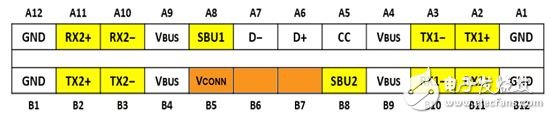
Figure 1: USB Type-C Interface Pin Diagram
Peripheral mode
Peripheral mode supports the transmission of analog audio or debug signals over the USB Type-C interface. In audio mode, an audio output source device (such as a cell phone or laptop) can transmit analog audio signals (R/L) via the USB 2.0 (D+/D-) pin while passing through the sideband channels (SBU1 or SBU2). One to receive the microphone signal from an external audio source. Peripheral mode is expected to support digital audio in the near future. Peripheral mode requires a simple DC-level voltage comparator to detect which peripheral mode is required by the link. This detection block will be implemented by the audio source device. Once detected, the audio source device needs to use an analog switch that supports the audio signal and isolate the USB 2.0 signal when transmitting audio over the same pin, as shown in Figure 2. Since the peripheral mode of the mobile phone/laptop is not mandatory, the consumer needs to read the electronic device's data in detail to determine whether it supports audio transmission via the USB Type-C interface.
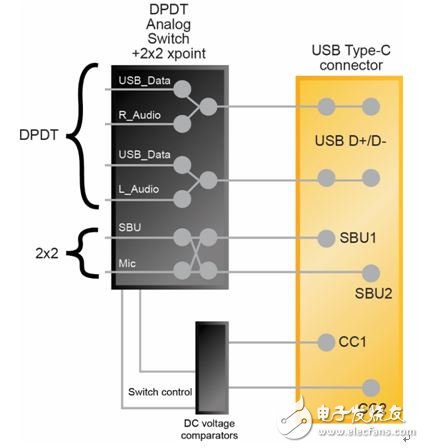
Figure 2: System Block Diagram - Support for Audio Peripheral Mode via USB Type-C Interface
Power Data Object (PDO) and Power Delivery Contract
The Power Data Object (PDO) is a packet containing voltage and current performance information that can be transmitted over the USB Type-C interface. Each USB Type-C interface (with the ability to support power) can send up to 6 PDOs when creating a new connection. The receiving device then screens the six PDOs and establishes a power supply protocol after determining the appropriate voltage and current pairing to achieve power transfer between the USB Type-C interfaces. The USB type-C interface supports a voltage range of 0V to 20V, which is increased or decreased by 50mV. The supported current range is 0A to 5A, which is increased or decreased by 10mA. The USB Type-C interface natively supports 5V @ 900mA power supply, and other parameters are optional. When purchasing power and power devices for the USB Type-C interface, you must carefully confirm their functions and requirements to achieve the fastest charging. Otherwise, consumers will likely encounter a situation where only one PDO matches, ie 5V @ 900mA (4.5W). Due to the above situation, future development will make it easier for users to match power and power equipment.
Alternative mode (structured VDM)
The alternate mode is another alternative to transferring non-USB data via USB Type-C interface negotiation. There are currently two standardized alternatives to the USB Implementers Forum - DisplayPort and MHL? , developed by the standards organization to which it belongs. Thunderbolt 3 is a private alternative model developed by Intel. DisplayPort and MHL are committed to connecting USB Type-C-enabled products to external displays. Thunderbolt benefits from Intel's latest Alpine Ridge controllers that integrate PCI Express Gen3 and USB 3.1 Gen 2 functionality, so additional data support is added. Floor. According to arstechnica, the Thunderbolt replacement model provides the highest level of protocol support on the USB Type-C interface with its advanced integrated features, native support for PCI Express Gen 3, USB 3.1 Gen 2, DisplayPort 1.2 and Thunderbolt. Thunderbolt 3 supports up to 40 Gbps and can drive two 4K 60 fps displays or one 5K 60 fps display.
DisplayPort pays more attention to video resolution and is committed to transmitting 8K resolution video over a single USB Type-C interface. DP1.3 can provide 32.4Gbps speed and support lossless video data. The VESA FAQ page provides information indicating that it can meet the transmission requirements of 8K 60 fps 4:2:0 video.
The second standardized alternative to the USB Type-C interface is MHL, which supports compressed or lossless video signals. Uncompressed, MHL delivers 24 Gbps for 4K 60 fps 12-bit color depth video transmission. With Display Stream Compression (DSC) technology, MHL can support up to 72Gbps and meet the bandwidth requirements of 8K 60 fps 4:4:4 video transmission, making MHL the first choice for effective video bandwidth. DSC is a line-based compression algorithm that provides a visually lossless solution while minimizing video latency after compression. Figure 3 shows an example of an image before and after using DSC.

Figure 3: The right image is 2.5x compressed according to the DSC specification, and the left image is uncompressed. It is difficult for the viewer to see the difference between the two.
In order to use the two standardized alternative modes described above, the system architecture engineer must first select the chipset that supports the selected standard. Intel is the exclusive supplier of Thunderbolt, and there are many suppliers of MHL or DisplayPort. System architecture engineers will also need alternative mode negotiation chips, such as Lattice's latest USB Type-C interface controller products. Since there is no mandatory requirement for the relevant mark, consumers need to read the product documentation before purchasing the product to find out which alternative modes the product supports, and avoid the situation where the DisplayPort product is purchased but connected to the MHL accessory.
Structured and unstructured Vendor Defined Messages (VDM)
Both structured and unstructured VDMs are built on SVID (Standard ID or Vendor ID) and approved by USB-IF, so you can be sure that both are unique. The standard ID is specified as a standardized alternative mode for the entire USB Type-C ecosystem (such as MHL and DisplayPort). The Supplier ID is unique and applies to a business and may not be known to the public.
USB Power Delivery (USB PD) messages/instructions are exclusively defined by either of the above standards or vendors. Structured VDM messages are extensible instructions that are defined in the USB PD specification and are the primary mechanism for entering and exiting alternate modes. Unstructured VDMs are completely defined by the vendor and are commonly (but not required) used in the entry into the surrogate mode.
For example, if a device enters an alternate mode, it may continue to send structured VDMs to manage the operation of the alternate mode. However, the requirements of some instructions are difficult to support with structured VDMs.
Consumer training
The key to the success of the USB Type-C interface is to educate consumers and develop their attention. The first time you face consumers, you should emphasize the new advantages of the USB Type-C interface:
·Plug and cable direction for both positive and negative.
Flexible and fast charging, supporting up to 20V and up to 5A according to the USB power supply protocol.
· Designed to support optional signal transmission modes such as audio headphones and video output.
When purchasing a USB Type-C charger, consumers need to confirm that the charger meets the device's fast charging function requirements (voltage and current) to enjoy the fastest charging experience.
There are no mandatory peripheral modes supported by mobile phones and laptops, so consumers need to verify that the product has the required features, such as whether the USB Type-C interface supports audio mode.
There is no mandatory label for the alternate model, so consumers also need to confirm which alternative mode or models (such as MHL, DisplayPort or Thunderbolt) the product supports.
Marketed USB Type-C products
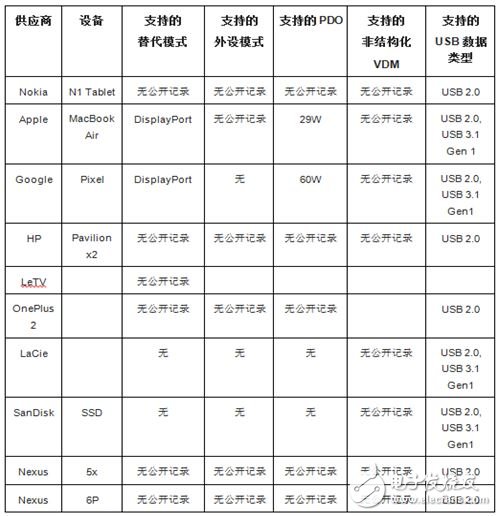
The end products listed in the table below have been announced to support USB Type-C. At the same time, the table also lists the characteristics recorded in the documentation for each product.
Main characteristics and advantages of Electrical Cable Protection Sleeve For Copper Harness
1) Lasts longer than cable ties
2) Reduce harness weight
3) Easy access for breakouts
4) Obstraction-free cable grooming
5) Will not burn, melt or support combustion
6) Extreme abrasion resistance
1. Copper foil shielding sleeving is woven with copper foil filament,it is used for various electrical and industrial fields where EMI shielding, excellent protection and lightweight are required.
2. It is lighter and more flexible than tinned Copper Braided Sleeving,it is a perfect conbination of economy and durability,it can be used as connectors with highly flexible and easily to install.
Electrical Cable Protection Sleeve
Metal Copper Electrical Sleeve,Braided Sleeve For Cable,Resistant Braided Sleeve Heat ,Braided Copper Expandable Sleeving
Shenzhen Huiyunhai Tech.Co.,Ltd , https://www.hyhbraidedsleeve.com