Here, the details of the failure of the electronic part are sorted out. The system level FMEA is mainly to establish conceptual problems and confirm the seriousness of the problem. At this level, you can grasp the different designs and the hardware and software FMEA behind the design.
This article refers to the address: http://
The so-called software and hardware strategy fault-tolerant design is based on the high RPA, unacceptable state, set Safety Goal to achieve security goals.
4) Battery unit status is summarized to the whole vehicle
a) normal customer use (driving, charging, parking & maintenance)
4.1 Unable to send normal status
(10 4 7) The battery system cannot communicate with the vehicle <= Vehicle Fault Tolerance Design
(10 4 4) Unable to communicate inside the battery system <= Vehicle Fault Tolerance Design / Battery System Fault Tolerant Design
(10 4 7) Electronic module loss of power <= vehicle fault tolerance design [standard voltage test software test]
(10 4 4) Sensor failure
(10 1 4) Communication crash (data transmission error) <= serial communication strategy
4.2 Intermittent transmission of normal status
(10 4 7) The battery system is intermittently unable to communicate with the vehicle <= Vehicle Fault Tolerance Design
(10 4 4) Battery system intermittent internal communication cannot be <= Vehicle fault tolerance design / battery system fault tolerance design
(10 4 7) Intermittent power loss of electronic module <= Vehicle fault tolerance design [Standard voltage test software test]
(10 4 4) Sensor intermittent failure
(10 1 4) Intermittent communication crash (data transmission error) <= serial communication strategy
4.3 Sending normal status information when fault occurs
(10 1 7) MCU failure <= Vehicle fault tolerance design / battery system fault tolerance design
(10 4 4) Sensor information error <= Vehicle fault tolerance design / battery system fault tolerance design
(10 1 4) Intermittent communication crash (data transmission error) <= serial communication strategy
(10 4 7) The battery system cannot communicate with the vehicle <= Vehicle Fault Tolerance Design
(10 4 7) Electronic module loss of power <= vehicle fault tolerance design [standard voltage test software test]
4.4 Intermittent transmission of fault information
(10 4 7) The battery system is intermittently unable to communicate with the vehicle <= Vehicle Fault Tolerance Design
(10 4 4) Battery system intermittent internal communication cannot be <= Vehicle fault tolerance design / battery system fault tolerance design
(10 4 7) Intermittent power loss of electronic module <= Vehicle fault tolerance design [Standard voltage test software test]
(10 4 4) Sensor intermittent failure
(10 1 4) Intermittent communication crash (data transmission error) <= serial communication strategy
4.5 Sending fault information when normal
(10 1 7) MCU failure <= Vehicle fault tolerance design / battery system fault tolerance design
(10 4 4) Sensor information error <= Vehicle fault tolerance design / battery system fault tolerance design
(10 1 4) Intermittent communication crash (data transmission error) <= serial communication strategy
(10 4 7) The battery system cannot communicate with the vehicle <= Vehicle Fault Tolerance Design
(10 4 4) Battery system intermittent internal communication cannot be <= Vehicle fault tolerance design / battery system fault tolerance design
(10 4 7) Electronic module loss of power <= vehicle fault tolerance design [standard voltage test software test]
4.6 Information is incorrect or not sent
(10 4 4) Unable to communicate <= Vehicle Fault Tolerant Design
(10 1 7) MCU failure <= Vehicle fault tolerance design / battery system fault tolerance design
(10 7 4) Sensor lost <= battery system position / structure
(10 4 4 ) Sensor accuracy problem <= battery system position / structure
5) Control and manage the battery cells in the battery system
a) Maintain SOC within the scope of work
5.1 SOC overcharge
(10 4 7) Sensor failure (harness, short circuit to 12V/GND, open circuit)
(10 1 7) MCU failure
(10 4 7) Algorithm error
(10 1 4) Intermittent communication crash (data transmission error) <= serial communication strategy
5.2 SOC over discharge
(10 4 7) Sensor failure (harness, short circuit to 12V/GND, open circuit)
(10 1 7) MCU failure
(10 4 7) Algorithm error
(10 1 4) Intermittent communication crash (data transmission error) <= serial communication strategy
b) temperature control within the range
5.3 Temperature is above safe range
(10 4 4) Insufficient heat dissipation
(10 4 7) Temperature sensor failure (harness, short circuit to 12V/GND, open circuit)
(10 4 4) Battery internal resistance is too high
(10 1 7) External temperature exposure overheating
(10 1 4) External heating
5.4 The temperature is too low during charging
(10 4 7) External cooling
(10 4 7) Temperature sensor failure (harness, short circuit to 12V/GND, open circuit)
c) battery voltage consistency maintenance
5.5 Voltage does not last (stable)
(7 4 7) Sensor failure (harness, short circuit to 12V/GND, open circuit) Charger failure Monomer acquisition circuit Contact resistance is too high Monomer internal resistance is too high Parallel monomer loss
5.6 Monomer voltage is too high
(10 4 7) Sensor failure (harness, short circuit to 12V/GND, open circuit)
(10 4 7) Charger failure
(10 7 7) The contact resistance of the single-chip acquisition circuit is too high
(10 4 7) The internal resistance of the monomer is too high
(10 4 7) Parallel cell loss
5.7 The cell voltage is too low
(10 1 4) Sensor failure (harness, short circuit to 12V/GND, open circuit)
10 1 7) Intermittent communication crash (data transmission error) <= serial communication strategy
(10 4 7) The main relay cannot be disconnected
(10 1 4) Battery pack short circuit
d) maintain the charge and discharge current within a certain range
5.8 Current is too high
(10 4 7) Charger failure
(10 1 4) Fuse failure
(10 4 4) Battery pack short circuit
5.9 Charging current is too low
summary:
a) A lot of the above is the ability to determine the safety situation from the experiment.
b) Details can go down to each sensor, MCU, power supply, and even serial communication & signal output
c) I have the opportunity, I have to do my own design carefully.
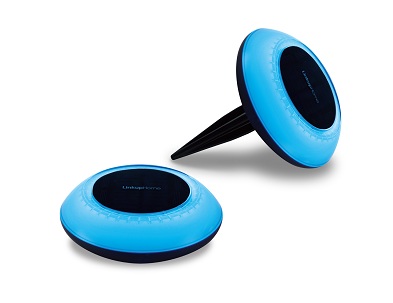
Smart solar outdoor light with both lighting and RGB colorful lighting, can be charged with USB and solar panel. Once it has sunlight, the solar panel can be automatically charged , the charging way is very environmentally friendly. We added a USB charging way so that it can be quickly charged via the USB cable in cloudy day or rainy day.
The outdoor light is solar-sensing, it will automatically turns off when in the bright enviroment, then begin to charge by solar. When the night comes, it will automatically turn on in the dark. Waterproof IP65 makes users no need to worry when using in the rainy day.
Equipped with a detachable plastic sticker, it can be used to decorate the lawn, garden, beach... After removing the plastic sticker, it can be placed on the table as an ambient light. They will be stars fall into your garden, twinkle in the dark and go off in the day. Automatic cycle colorful mode makes parties begin at anytime and anywhere.

Our LED products can meet global quality standards and pass European testing by TUV Rheinland. Bulbs have certifications such as EMC, RED, LVD, ROHS, REACH, ERP and FCC.
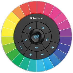
With the exclusive designed 2.4G remote controller, get you off the switch and turn on / off the lights anywhere, one remote controller can set 4 groups, each group is recommended to match up 8pcs bulbs, one remote controller can max control 32 bulbs. This remote controller is suitable for all 2.4G versions of RGBW products under [linkuphome".
The remote control uses colorful touch buttons, the color touch buttons are comfortable and sensitive. The remote controller has the functions of grouping, lighting, brightness adjustment, color light automatic cycle mode, three cycle speeds can be choosed. The wireless control distance is around 20 meters. Low power consumption makes the remote controller only need 4pcs AA batteries, but can be used for two years.

Description: RGB Outdoor Solar Lamp with 2.4G Control
Product Model No. C2
Product dimension: 155mm *165mm
Material: ABS+PC
Lamp Color: 8pcs RGB lamp beads+4pcs Warm White lamp beads
Lamp Current: 15-20mA
Power: 0.5W (15LM)
Battery Capacity: 1000mA (Li battery included)
Battery Voltage: 3.7V
Battery Duration: 9h(by USB charge for 1.5h) , 5h(by solar panel for whole sunny day)
Solar Panel: Monocrystalline silicon
Solar Panel Voltage: 6V
Solar Panel Output: 130mA
Waterproof Level: IP65
Control Qty: 1-32pcs
Packing: color box
Warranty: 1 Year
Charge Mode: Solar Panel and USB
Control Distance: 20m
Color box size: 22.2*20.6*5cm
G.W. of Unit: 0.55kg
N.W. of Unit: 0.34kg
Certification: CE(EMC,RED) ROHS,IP65,FCC
Description: 2.4GRF Wireless RGB Remote Controller
Product Model No.: R1
Product dimension: 105mm *33mm,
Product Net Weight: 150g
Material: ABS
Battery: 4*AA Battery (not included)
Working Voltage: 6V
Standby Power: 3 mW
Frequency Band: 2400-2483.5MHz/2.4GHz
Control Distance: 20m
Control bulb qty: 1-32 pcs
Packing: color box
Warranty: 1 Year
Color box size: 16.7*14.7*4.5cm
G.W. of Unit: 0.22kg
N.W. of Unit: 0.15kg
Outdoor Lamp With Remote Control
Outdoor Lamp With Remote Control,Remote Control Outdoor Lamp,Waterproof Outdoor Lamp,Remote Control Outdoor Colorful Lamp
Ningbo Homey Photoelectric Technology. Co., Ltd , https://www.linkuphome.com