1 Introduction
In recent years, embedded development has been rapid, and the event-triggered programming method using the 51-chip dead loop has gradually failed to meet the requirements of enterprise stability and security. At present, embedded system software includes VxWork, Linux, WinCE, μC/OS-II, etc. For cost and technical considerations, microcontrollers often do not select them for design. In practical applications, it is often faced with multiple peripherals and multitasking at the same time, and their mutual scheduling is essential. Time-triggered embedded systems are such simple and practical operating systems.
This paper designs a time-triggered multi-task scheduler based on AVR microcontroller and applies it to practice. The scheduler uses a message to cause the microcontroller to switch between multiple tasks and devices.
2. Structure characteristics of AVR microcontroller
AVR is currently using the series of ATmega128 as an example. It uses Harvard architecture, RISC instruction set, low power consumption, and rich on-chip resources, which greatly simplifies the peripheral circuits and makes the system more stable and reliable. Its features provide a good hardware guarantee for embedded system design.
3. Comparison of two embedded trigger modes
In an embedded system, two essentially different scheduling methods are typically used: event triggering and time triggering. The event triggering method is often implemented by using multiple levels of interrupts, and its occurrence time is random; while the time triggering method is driven by a global clock, and the behavior of the system is determined in terms of function and time, that is, predictability.
3.1 Problems with event triggering
Embedded system developers have a misconception that interrupt events are never lost, which often has disastrous consequences for the products being developed. The loss of interrupt events is an indisputable fact in practical applications. There are many reasons for this, but there are two reasons: internal and external. The external cause refers to the cause of the external system. Here, the interrupt source signal is lost or too frequent. The internal cause can be divided into hardware and software reasons. The hardware cause is mainly caused by the interrupt nesting capability of the embedded device used. The reason is mainly caused by the error setting of the task interrupt priority and the improper processing of the task when the developer is programming.
For example, interrupt 0 is a high priority interrupt and interrupt 1 is a low priority interrupt. The interrupt service routine activated by the high priority interrupt cannot be interrupted by a low priority interrupt. Thus, the response to the second interrupt will be delayed, and in some cases it may be completely ignored.
If multiple interrupt sources may generate an interrupt at a "random" time interval, the interrupt response may be missed. In fact, with several valid interrupt sources at the same time, it is almost impossible to create program code to properly handle all possible interrupt combinations. And handling multiple events at the same time not only increases system complexity, but also reduces the system's ability to predict behavior in all situations. As for the efficiency of use, Metzner discussed and concluded that an event-triggered system with 27 tasks and RM scheduling algorithm has a CPU utilization rate of only 18%.
3.2 Advantages of time triggering
In this system, designers can ensure that only one event is processed at a time by carefully arranging the controllable order. Its predictability makes it the first choice for safety-related systems.
Kopetz first proposed that using a time-triggered cooperative scheduler would make the system very predictable. In addition to improving reliability, using this method helps to reduce CPU load and memory usage.
4. Time-triggered embedded system design
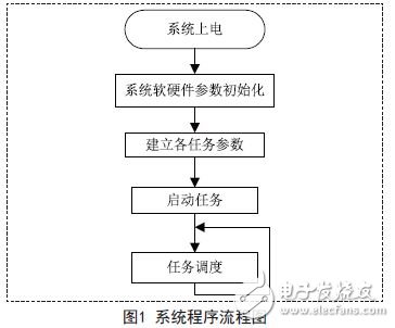
In the scheduler, the timer settings are separated and independent of the compiler's data type and the number of bits in the processor. This part can be easily ported to multiple hardware platforms. The overall block diagram of the system is shown in Figure 1:
4.1 Message Queuing
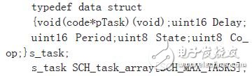
Message Queuing is the core of the scheduler. It is a user-defined data type that contains the information needed for each task. Try to store it in the DATA area for quick access.
For a time-triggered hybrid scheduler, the following data structure is used, with a memory overhead of only 8 bytes for each task. Even with a 32-bit processor, the overhead per task is only 14 bytes.
4.2 Scheduler Timer Initialization Function
This function is used to generate a timing scale that drives the scheduler.
The Amega series of ATmega128 microcontrollers selected in this paper have four timers (two 8-bit, two 16-bit), either of which can be used to drive the scheduler.
Void SCH_Init_T0(void){Delete each task one by one; stop timer 0; set time size function; enable timer 0 mode; start timer 0;}
Note: The total interrupt cannot be turned on during this time, ie:
SREG=0&TImes;80 or SEI(); the scheduler must first set a default time slice, which is not a trivial matter. Excessive time slices can cause the system to perform poorly in response to interactive behavior; time slices are too short and can significantly increase the scheduler processing time, while leaving the task running for a short time.
According to the author's experience, a preferred time slice is slightly longer than the time required for a typical interaction, so that most processes are completed in one time slice. After repeated trials, the time slice selection is more efficient between 1 and 5 ms, which can meet the requirements of response speed and minimize the task execution time. This time is related to the number of tasks and the running time of the task, and the specific size depends on the situation.
Portable power supply humanized output port design: AC dual output port 220V output, to solve multi-channel power demand; DC 24V, 12V cigarette lighter, dual 5V USB output, more widely used. Can meet the needs of most electrical appliances, such as energy storage system for LED Light,energy storage system for outdoor, energy storage system for medical equipment,mobile phones, telephones, digital cameras, mobile hard drives, digital cameras, tablets, laptops, car starters, pumps, postal and telecommunications, environmental instruments Etc; can also be used in the following areas such as: finance, first aid, excavation, exploration, military, science, media, tourism, disaster relief, medical assistance, environmental protection and areas with widespread power shortages.
Outdoor Small Energy Storage System
Solar Storage Battery,Small Solar System,Energy Storage System For Computer,Energy Storage System For Power Tools,Portable Small Electric Station,Multifunctional Lithium Generator
Shenzhen Enershare Technology Co.,Ltd , https://www.enersharepower.com