In gasoline engine fuel injection and ignition control systems, high-power triodes or FETs and their auxiliary circuits are usually used to generate large drive currents to drive the injectors and spark plugs. However, for a four-cylinder gasoline engine, there must be four injectors and a spark plug drive circuit respectively. Thus, the drive circuit is bulky, relatively stable, and complex in structure. MC33810 is a four-cylinder gasoline engine dedicated fuel injection and ignition drive integrated chip introduced by Freescale. The chip has the characteristics of small size, light weight, high integration and good economy [1].
1 Structural principle
MC33810 chip has power supply module, power reset module, SPI serial input and output interface module, parallel control input module, pulse width modulation control module, standard / maximum coil current comparison module, ignition duration comparison module, injector drive module And the ignition gated pre-driver module can perform SPI communication with the gasoline engine ECU, accept the parallel control of the ECU, realize the fuel injection and ignition function, and can feedback the ignition current and the ignition duration to prevent damage to the ignition coil, and the internal circuit has Overvoltage, overcurrent, overheat protection function [2].
2 application circuit design
2.1 ECU power management circuit design
The MC33394 is a high-performance power management IC that operates from +4 V to +26.5 V and is ideal for powering engine ECUs. It contains a +5 V/+3.3 V/+2.6 V voltage regulator module for direct output of +5 V, +3.3 V and +2.6 V. Its application circuit is shown in Figure 1. 
The battery is powered by an external power supply, typically between +12 V and +14 V. The output voltage of the VPRE port is +5.6 V, the output of the VDDH port is +5 V@100 mA, and the output of the VPRE1, VPRE2, and VPRE3 ports is +5 V@100 mA. The VPP port can output +5 V@150 mA or +3.3 V@150 mA to supply power to the external Flash ROM. The VDD3_3 port is connected to a triode to form a power supply of +3.3 V@120 mA. Two transistors are connected to the VDDL port to form a +2.6 V@40 mA power supply [3]. Therefore, the MC33394 can fully meet the power management and power requirements of the MPC564.
This article refers to the address: http://
2.2 ECU system circuit design
The ECU system circuit with MPC564 as the core includes: power supply circuit, reset circuit and crystal oscillator circuit. The power supply circuit mainly provides +5 V and +2.6 V voltage to MPC564 from MC33394. The power interface of MPC564 is: VDDH1~VDDH8, connect +5 V power supply; VDD1~VDD13, QVDDL1~QVDDL15, connect +2.6 V power supply; GND1~ GND105, ground. The reset circuit interfaces are: power reset PORESET, hardware reset HRESET, and software reset SRESET. Since they are all active low, a conventional resistor-capacitor reset circuit is used. The crystal oscillator circuit consists of a crystal oscillator, a resistor, and a capacitor. The external crystal selects 4 MHz, the crystal feedback feedback resistor selects 10 MΩ, and the capacitor selects 22 pF. The PLL phase-locked loop circuit can generate an internal clock of 40 MHz and a system clock of 20 MHz [4]. Its system circuit is shown in Figure 2. 
2.3 MC33810 interface circuit design
The MC33810 chip has a serial input/output port (SPI), four drive input ports (DIN0 to DIN3), four output ports (OUT0 to OUT3), four gated pre-drive inputs (GIN0 to GIN3), and outputs. Port (GD0~GD3), 4 feedback voltage detection input ports (FB0~FB3), one ignition coil maximum current output flag (MAXI), one ignition coil standard current output flag (NOMI), one resistor induction positive port ( RSP) and a resistor-sensing negative port (RSN) [2]. The serial input and output port is mainly used to send and receive control commands of the ECU, and can be directly connected to the SPI port of the MPC564. The drive input and output ports are mainly used to control the opening and closing of the injector. The input port is connected to the ordinary I/O port of the MPC564, and the output port is connected to the injector. The gated pre-drive input and output ports are mainly used to control the opening and closing of the power tube to control the ignition of the spark plug, so the input port is still connected to the ordinary I/O port of the MPC564, and the output port controls the base of the power tube. In this way, the fuel injection and ignition control commands can be controlled either by the ECU issuing the SPI command or directly through the parallel port. The feedback voltage detection port is mainly used to monitor the collector terminal voltage of the power tube during ignition. The voltage is divided by two resistors, and the resistance ratio is about 9:1 (36 kΩ and 4.02 kΩ can be selected). The maximum current output flag of the ignition coil is mainly used to provide the ECU with the maximum current output signal reference mark of the ignition coil. The standard current output flag of the ignition coil is mainly used to provide the ECU with the standard current signal reference mark of the ignition coil to prevent the ignition coil from being damaged due to excessive current, so it can be directly connected to the ordinary I/O port of the MPC564. The resistance-sensing positive port and the resistance-sensing negative port are mainly used to sense the magnitude of the resistance current passing through the two ends. Here, the magnification is selected to be 1 time, and the resistance is selected to be 0.04 Ω, as shown in FIG. 
3 driver design
3.1 Fuel injection program design
Gasoline engine injection must determine the fuel injection advance angle and fuel injection. The fuel injection advance angle of the four-cylinder gasoline engine is generally fixed and is located at 64° before the top dead center of the exhaust stroke, so it can be determined based on the crankshaft position signal from the crankshaft position sensor [5]. The amount of fuel injected is determined by the duration of the injector needle opening, that is, the fuel injection pulse width. The fuel injection pulse width is collected by the ECU through the actual data of the intake manifold absolute pressure, engine speed, manifold intake air temperature, throttle position, battery voltage and other signals, and then determined according to the MAP map. When the injection timing arrives, the ECU directly issues an injection command through the SPI port or the parallel port, and then turns on the timer to determine the duration of the timing injection. When the fuel injection is completed, the fuel injection command is directly turned off.
The MC33810 has internal overheat protection and timing protection commands to protect the injector from overheating and excessive injection time. Here, for example, the first cylinder injector is driven by the SPI port, and the protection command 0E10H and the fuel injection command 3001H are used. The fuel injection program flow chart is shown in Figure 4. 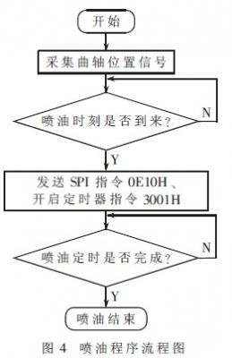
3.2 Ignition program design
The gasoline engine ignition must determine the ignition advance angle and the ignition closing angle. The ignition advance angle is mainly determined by the engine speed, load and the octane number of the gasoline [6]. When the octane number of gasoline is constant, it is only necessary to pass the test to establish the MAP map of the engine speed, the throttle position and the ignition advance angle. The size of the ignition closing angle is mainly determined by the ignition frequency of the engine. The higher the ignition frequency, the faster the engine speed. Therefore, the ignition advance angle and the ignition close angle can be determined by the ECU collecting the engine speed sensor and the throttle position sensor signal.
The MC33810 has the function of selecting the ignition closing angle (ignition duration), ignition current amplification factor, ignition standard current, and maximum current parameter setting. The appropriate ignition parameters can be selected according to the MAP map. Here, to drive the first cylinder ignition as an example, the ignition duration is set to 32 ms, the ignition mode selection command is 1000 H, the multi-cylinder ignition duration is allowed to overlap, and the current is amplified by 1 time, the ignition command is 49 CDH. The end of ignition filter setting 4 滋 s command is 5001 H. The ignition standard current is 5.5 A, the maximum current is 14 A, and the ignition duration is allowed to overlap by 35%. The DAC command is 688AH. The ignition program flow chart is shown in Figure 5. 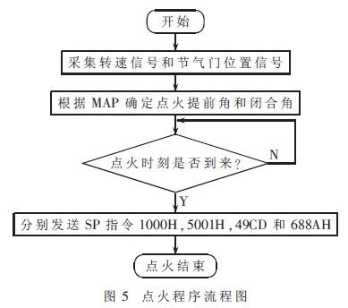
The MC33810 can be combined with the MPC564 to form the fuel injection and ignition control circuit to achieve the following functions:
(1) Directly use the MC33810 to drive the injector and ignition coil of the four-cylinder gasoline engine, eliminating the need for complicated drive circuits;
(2) MPC564 can choose SPI interface drive or parallel port drive according to actual needs, and the drive mode is flexible;
(3) MC33810 can send feedback monitoring signal of ignition drive current to MPC564 to protect ignition coil;
(4) The MC33810 has overvoltage, overcurrent and overheat protection inside, and the drive circuit is stable and has a long service life.
The test shows that the MC33810 can better drive the fuel injection and ignition circuit in the four-cylinder gasoline engine, which has certain practical significance and good application prospects.
Socket With LED Lamp is TOUKOO patent product. Assembling power extension, USB charger and lighting in one item which is easier for your daily needs.
Touch switch LED lamp 3W 300-350LM.
Besides the ten lamp model, customized design is welcomed as well. Color can also be customized, giving you diversified choices.
Fireproof ABS Plastic, PVC copper cable, Use standard plug. Easy and safe to use for elderly and children.
Socket With Led Lamp,Electrical Socket,Socket With Led Table Lamp,Led Decorative Lamp
ZhongShan JITONGLONG Plastic Hardware Co. Ltd. , https://www.toukoo-electronics.com