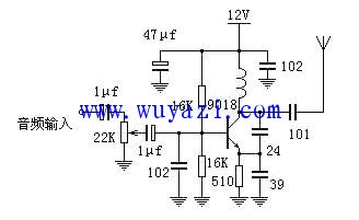
The 9018 is a high-frequency, low-power NPN silicon transistor with a characteristic frequency (fT) of up to 1.1 GHz. It is commonly used as an FM transmitter transistor due to its excellent performance at high frequencies. This makes it a popular choice among hobbyists and electronics enthusiasts for building simple radio transmitters.
The following diagram shows a single-transistor FM transmission circuit using the 9018. This design is straightforward and ideal for experimentation or temporary use. As you can see from the schematic, it's a classic three-point capacitor oscillator configuration. However, it's important to note that the 9018 is not specifically designed as an emitter follower transistor. As a result, the circuit may experience some frequency drift during operation. The higher the operating current, the more pronounced this drift becomes.
To build the circuit, a coil is wound with 6 to 8 turns of 1 mm enameled wire around a φ32mm drill bit. This inductor is tuned to cover the entire FM broadcast band, which ranges from 88 MHz to 108 MHz, making it suitable for standard FM radio reception. By adjusting the tightness of the coil, you can fine-tune the transmission frequency. In open areas, this simple transmitter can reach a distance of approximately 100 meters when using a dipole antenna. It's a great project for learning about RF circuits and basic wireless communication.
Pet Velcro Braided Sleeve,Pet Braided Sleeving,Pet Expandable Braided Sleeving,Cable Protection Sleeve
Shenzhen Huiyunhai Tech.Co., Ltd. , https://www.cablesleevefactory.com