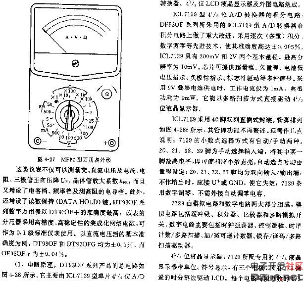
Hey there! I just came across this old MF30 multimeter circuit diagram that I thought might be interesting to share. It's always fascinating to take a peek under the hood of these classic devices and see how they work. I've included two images here — the first one is a bit smaller, and the second one gives you a closer look at the detailed circuitry.
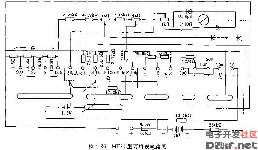
The second image really helps break it all down. As you can see, the design is quite intricate, with various resistors, diodes, and other components all working together to measure voltage, current, and resistance. It’s a great example of how analog multimeters were built back in the day.
Looking at this now makes me appreciate the craftsmanship that went into these tools. Even though modern digital multimeters are more precise and user-friendly, there’s something special about understanding the analog technology behind them. If you’ve ever tinkered with electronics, you’ll know how valuable it is to grasp the fundamentals like this.
Anyway, hope you found this as interesting as I did! Let me know if you have any questions or thoughts about it. Happy tinkering!
ceramic piston
Yixing Guangming Special Ceramics Co.,Ltd , https://www.yxgmtc.com