Three times and five times three-stage tubes into the wood three points to talk
Teacher Zhang Fei takes you to answer questions
Question one
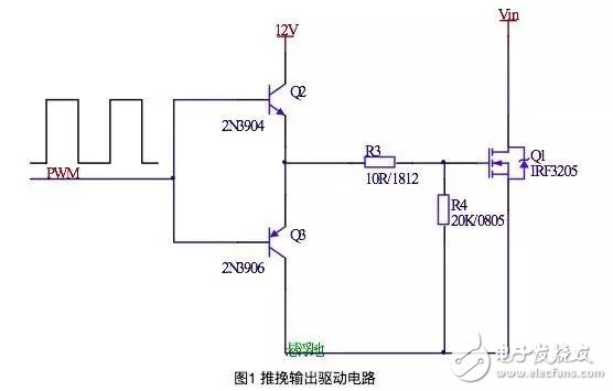
Problem 1: In the push-pull output driver circuit, the maximum reverse voltage at the EB terminal of the transistor is Veb = 6V (NPN). When the switching signal is low, the gate voltage is 12V during discharge, and the voltage drop exceeds 6V. Isn't the transistor burned out?
Answer: This is derived from process analysis. The rise and fall edges of PWM are time-consuming, and the diode between BE has a 0.7V voltage drop clamp function. During normal operation, when driving PWM from 0 to 12V, the N-tube can be turned on as long as it is greater than 0.7V, and the emitter follows. Meanwhile, the P-tube is completely turned off due to the -0.7V negative voltage; when PWM transitions from 12V to 0V, once the voltage drop of the P-tube reaches 0.7V, the conduction begins, and the E-P pole decreases along with the decrease of the B-P pole voltage. At this point, the negative pressure of the N-tube's BE becomes -0.7V, thus being completely cut off without exceeding 6V, ensuring safety.
Question two
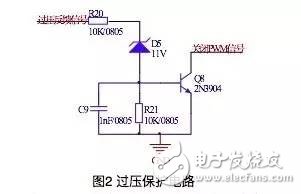
What is the understanding of the overvoltage protection circuit (partial circuit) in the figure below?
Answer: Assume the normal output voltage is 12V. When there’s an overvoltage situation, the Zener diode conducts with current flow, turning on the transistor, resulting in a low output to shut off the PWM signal. The overvoltage threshold is primarily determined by the Zener diode. Typically, a Zener diode requires about 2mA of current to achieve voltage regulation. Adjusting the Zener diode allows for significant threshold adjustments. R20 and R21 perform resistance voltage division, which can influence the pressure threshold within a certain range. Another role of R20 is current limiting; the capacitor C9 absorbs peak voltages while stabilizing the voltage and providing a certain delay.
Question three
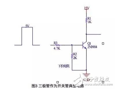
When the transistor operates in the switching state, what is the purpose of the pull-up resistor and the pull-down resistor?
Answer: 1. To prevent high-resistance states from affecting the normal operation of the circuit and causing safety issues; 2. To provide a discharge circuit for the transistor's interelectrode capacitance; 3. To offer a bleed circuit for static electricity and lightning, protecting the device. According to engineering experience, it is generally appropriate to select a resistance of around 2K.
Question four
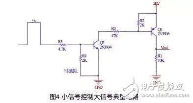
How does the small signal from the microcontroller control large signals as shown in Figure 4?
Answer: Since Q1 is connected to a large voltage of 50V, directly controlling it would require a high driving voltage, which the microcontroller cannot handle. Thus, we can adjust our approach by adding a switch at the Q1 control end, which acts like a large resistance. When the switch is open, the resistance tends toward infinity, meaning the drive terminal voltage is 50V, keeping Q1 open; when the switch is closed, the resistance approaches zero, allowing Q1 to conduct. This method enables the desired circuit function. Therefore, the front switch can be implemented using an NPN transistor, and the R3 resistor is used for current limiting.
Question five
Regarding the Zener diode, if it doesn’t reach the regulation value (e.g., 5.6V), is there no current flowing?
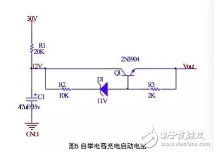
Answer: These semiconductor devices have a leakage current, though it is minimal and negligible. Now let’s analyze the circuit in Figure 5: C1 is the bootstrap capacitor. The purpose of this circuit is to charge C1 via R1 with a 30V input, charging it to 12V and supplying power to the back circuit. Here, the characteristic of the Zener diode is utilized—no current flows until the voltage reaches 11V. However, this circuit is more theoretical, as the transistor operates in an amplification state, leading to a large voltage drop between CEs (approximately 12V), resulting in significant losses. Additionally, the R3 resistor in the diagram could be omitted.
In summary, each component in electronic circuits serves specific purposes, whether it’s protecting transistors from voltage spikes or ensuring proper signal transmission. Understanding these principles helps engineers design more robust and efficient systems. For example, in the case of Zener diodes, their precise regulation depends on reaching their breakdown voltage, but they still allow for minor current flow even below this threshold. Meanwhile, resistors play crucial roles in managing currents and voltages, ensuring the safety and reliability of the entire circuit.
Solar Panel ,Flexible Solar Panels,Portable Solar Panels,Sunpower Solar Panels
zhejiang ttn electric co.,ltd , https://www.ttnpower.com