The KT88 has gained popularity in recent years due to its high output power, but some users find the sound quality lacking. It tends to sound loud without much clarity, which suggests poor balance in frequency response and insufficient detail in sound pressure. This issue is often attributed to an overemphasis on midrange frequencies compared to highs and lows, along with limited dynamic range. To address this, using a direct heat-pipe drive can significantly improve performance.
The 4PIS employs an RC-coupled voltage amplification circuit, which inherently requires an inverter when driving a push-pull output stage. Additionally, resistive loading limits the dynamic range of the 4PIS, affecting the output stage's performance. By adopting a 4PIS power amplification state and driving it through a transformer, optimal load matching is achieved. This setup allows for low distortion and strong signal drive on the ideal load resistance. The drive transformer also serves as an inverter with a 1:1+1 ratio, enabling the use of the A.ABI-type high-power output stage.
Compared to a small power tube used as a driver stage, the concepts of voltage amplification and power amplification are entirely different. In the AB1 class output stage, no external power drive is required, and the driver stage operates at its best impedance match, maximizing dynamics and minimizing distortion. Designing a power tube in a voltage amplification state focuses on achieving high-voltage output, which necessitates large load resistors or inductors. However, any mismatch in impedance makes it difficult to input high voltages, leading to a small linear region and increased nonlinear distortion.
A power amplifier operating in an impedance-matched state functions as a driver stage, with a lower optimum load impedance—typically below 5000Ω, as seen in this example where the 4PIS is only 3000Ω. This ensures sufficient linear working area. With such a low load impedance, the primary inductance of the drive transformer doesn’t need to be very large to support Hi-Fi playback’s low-frequency extension, simplifying the winding process. Previously, the primary inductance was usually between 50H and 150H, wound in a 1:1 ratio, with many turns increasing distributed capacitance and "big public" issues.
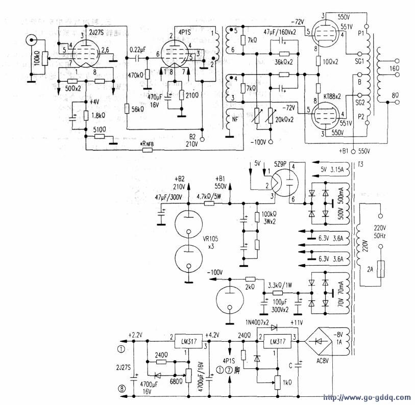
This schematic shows a 2xKT88 ultra-linear 50W post-amplifier circuit driven by the 4PIS in power mode. Each stage has unique characteristics:
First, the output stage features 2xKT88 operating in super-linear mode, based on data from the British GE company. The plate and G2 voltage is 550V, static current is 2x50mA, gate negative voltage is -72V, and static plate dissipation is 27.5W per tube. The load impedance is 4.5kΩ, with a second-gate tap ratio of 40% and -9dB negative feedback. At a grid input of 2x70Vp-p, the output is 100W with about 2% THD. At 2x52Vp-p, the output is 52W with THD under 1.5%.
Second, the 4PIS driver stage operates in a five-pole class A power amplification mode. Plate voltage is 210V, second-gate voltage is 210V, total cathode current is 32+6.5mA, and gate negative voltage is -8V. Using a 210Ω resistor, when a 7Vp-p signal is applied, the output is around 1.5W. At the optimal load of 3500Ω, the output voltage is 72.5Vrms (101Vp-p). The drive transformer has a 1:1+1 turn ratio, with 7kΩ resistors on each secondary side, resulting in 3.5kΩ impedance on the primary. This provides two anti-phase signals for the final stage.
Third, the first stage and negative feedback design use a 2127S three-pole RC-coupled amplifier. The 2J27S uses a 210V power supply, with a 56Ω load resistance. Its open-loop gain is around 14 times, and the 4PIS driver stage has a similar gain, making the pre-stage gain about 196 times. To achieve a 50Vp-p drive signal, the input sensitivity should be 255mVp-p. However, this is too high for a pure power amplifier. A more typical input sensitivity is 500mV–1Vp-p to reduce noise and distortion. If set at 800mV, the front stage needs a 60x gain. An additional +10dB gain allows for -10dB negative feedback between the pre-stage and driver stage, balancing the overall gain and improving stability.
Fourth, the power supply includes two high-voltage outputs. The first supplies 550V to the UL output stage, using a full-wave vacuum rectifier 529P with a 45-second delay to protect the KT88 cathode. A filter capacitor and internal resistance help reduce ripple. The front stage’s 210V power supply is stabilized using VR105 regulators to ensure low noise and high stability for the 4PIS and 2J27S tubes.
Finally, the machine requires two custom-made transformers. The output transformer T is designed for 4200–4500Ω primary impedance and 50W output, while the input drive transformer T1 is self-wound. The T2 transformer is a Class A output type, using E20 cores and careful winding techniques to ensure symmetry and stability. The B+ and C- voltages are adjusted manually using LM317 regulators, and the KT88 gate negative voltage is fine-tuned for balanced operation.
Frame For Iphone 14,Metal Frame For Iphone X14Promax,Iphone X14Promax Frame With Glue,Original Frame For Iphone X14Promax
Shenzhen Xiangying touch photoelectric co., ltd. , https://www.starstp.com