When serial communication between a PC and a DSP is implemented, the serial communication interface (SCI) module of the DSP and the SCI multiprocessor communication protocol (ie, idle line mode and address bit mode) can be directly used in the same serial line. To achieve communication between multiple processors, serial communication can also be implemented using the SCI asynchronous communication mode. Although these two methods can easily realize serial communication, they all need to occupy more hardware and software resources of the system. 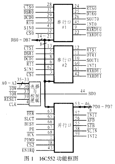 Therefore, it is not suitable for applications with high real-time requirements and tight system resources. In the development of the power active filter experimental system, the author successfully solved this problem by using the asynchronous communication chip 16C552. This paper will introduce the implementation method of this scheme from two aspects of circuit structure and software programming.
1 Introduction to 16C552
1.1 Functional characteristics and structure block diagram
The 16C552 is an asynchronous communication chip produced by TI (TL16C552) and VLSI (VL16C552). It has two enhanced universal asynchronous communication unit channels and an enhanced two-way printer port. It supports two modes, TL16C450 and FIFO, with 16 bytes. FIFO reduces CPU interrupts; each channel has independent transmit, receive, line status, and set interrupt functions, as well as independent MO-DEM control signals, programmable serial data transmission format (including data bit length, parity) Mode, stop bit length) and programmable baud rate generator; in addition, each channel's data and control bus also has a three-state TTL drive function.
TL16C552AM is TI's 68-pin PLCC (Plastic Leaded Chip Carrier) package chip, its pin and functional block diagram shown in Figure 1. As can be seen from the figure, its serial port mainly performs two functions, one is to convert the serial data received by the peripheral or modem into parallel data; the other is to convert the parallel data of the CPU into serial data for transmission. . During normal operation, the CPU can read the status information of the 16C552 at any time to report the type and status of the 16C552 transmission operation, including various error statuses such as parity, overflow, framing error and FIFO error. In addition, the 16C552 also has a complete MODEM control function, and has CTS, RTS, DSR, DTR, RI, DCD and other signal terminals.
The 16C552 has a comprehensive interrupt system that automatically sets priorities. Its serial port and parallel port can work independently in both interrupt and query modes.
1.2 16C552 internal register
There are 12 single-byte registers inside the 16C552. These registers occupy 8 I/O port addresses, and their addresses are determined by A0~A2. Some of these registers share an I/O port address. The shared I/O port can be distinguished by the read/write signal and the D7 bit of the Line Control Register (LCR). The details are listed in Table 1. The serial channel can only be accessed when CS0 or CS1 of the 16C552 is low.
Table 1 Internal registers of the I6C552
| DLAB | A2 | A1 | A0 | Symbol | Register |
| L | L | L | L | RBR | Receive buffer register |
| L | L | L | H | THR | Transmit holding register |
| L | L | L | L | IER | Interrupt enable register |
| X | L | H | H | IIR | Interrupt identification register |
| X | L | H | L | FCR | FIFO control register |
| X | L | H | H | LCR | Line control register |
| X | H | L | L | MCR | MODE control register |
| X | H | L | H | LSR | Line status register |
| X | H | H | L | MSR | MODEM status register |
| X | H | H | H | SCR | Cache register |
| H | L | L | L | DLL | Divisor latch low |
| H | L | L | H | DLM | Divisor latch high |
The specific provisions on the contents of each register are limited to the length, and will not be described in detail here. Those who are interested can refer to TI's related product information, but in serial communication applications, it is necessary to focus on FCR, LCR, IER and other registers. Content. In addition, in practical applications, the D4 bit in the MODEM control register may sometimes be ignored. This bit is the self-test loopback status control bit, which can be used to control the self-test of the serial port. Therefore, after the self-test is completed, This bit should also be reset to ensure proper system operation.
2 communication system hardware interface circuit
The hardware interface circuit of this system is shown as in Fig. 2. Among them, the address decoding circuit can be implemented by different circuits according to actual needs. In order to make the system flexible and convenient, a CPLD is used in this solution to allocate the address of the system. The reset circuit can be implemented by a dedicated reset chip or by a pull-up resistor. The external crystal oscillator can be selected by itself, and then the high and low bits of the divisor latch are set according to the crystal frequency to obtain the correct baud rate of the communication system. The crystal oscillator used in this system is 8MHz. In addition, since the 16C552A has two serial channels and a standard parallel port, their use in hardware and software should be noted. It is recommended to select the chip without the port to be connected to the high level (the 16C552A chip is selected as active low) to avoid errors. 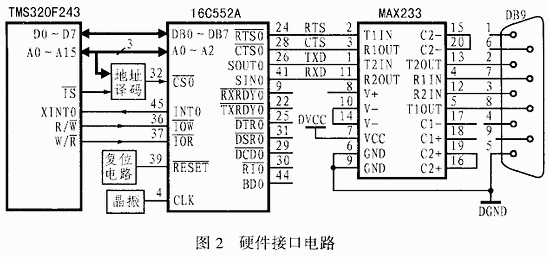
3 serial communication software design
3.1 Communication protocol
The communication protocol of this design includes the following points:
(1) The baud rate is 9600.
(2) The communication command consists of 2 bytes: the first byte is the sync byte 0XFF; the second byte is the command code, which is mainly used to indicate various control commands.
(3) Each byte includes 8 data bits and 1 stop bit, no parity.
(4) During the communication process, the host computer sends a synchronization command to the TMS320F243, and the TMS320F243 immediately responds after receiving it, and retransmits if the response is incorrect.
(5) When the communication program sends a control command to the TMS320F243, the TMS320F243 returns to receive the correct response signal; when the communication program queries the TMS320F243 for the system parameter command, the TMS320F243 returns the required data according to the specified format.
Both the PC and the TMS320F243 use asynchronous communication. The PC uses event-driven mode to receive data. The TMS320F243 uses interrupt mode to receive data and uses the query method to send data. 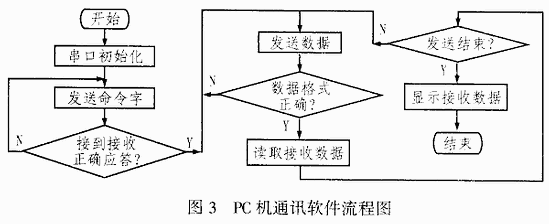
3.2 Upper and lower computer communication software design
There are at least three ways to write a serial communication program on a PC, namely assembly language, C language, and Visual Series communication control (MSComm). In comparison, the Visual Series communication control can easily and efficiently complete programming tasks with a small amount of code. In practical applications, the serial communication program of the PC can be written based on the communication control MSComm in Visual Basic (VB) 6.0, and the lower computer (F243) software is written in assembly language. The serial port program flow of the upper and lower machines is shown in Figure 3 and Figure 4, respectively. The initialization procedure for the 16C552 is as follows:
;THE 16C552 INITIALIZATION PROGRAM
C552_INIT:
LDP #00h
SPLK #83h, GSR0
OUT GSR0, 0E003h ; set LCR
SPLK #34h, GSR0
OUT GSR0,0E000h ;Set DLL
SPLK #00h,GSR0
OUT GSR0,0E001h ?; Set DLM
SPLK #03h, GSR0
OUT GSR0,0E003h ?; Set LCR
SPLK #08h, GSR0
OUT GSR0,0E004h ?; Set MCR
SPLK #01h, GSR0
OUT GSR0,0E002h ?; Set FCR
SPLK #01h, GSR0
OUT GSR0,0E001h ? ;Set IER
RET
Figure 4
4 Conclusion
In this paper, the serial communication method between PC and DSP is studied by using asynchronous communication chip 16C552. The author has developed its serial communication software and debugged it in the experiment. The software is not only flexible and convenient, but also can use the 16C552 FIFO mode to achieve large data volume transmission and reception, thereby reducing the interruption of the DSP and alleviating the shortage of system resources.
Guangzhou Fengjiu New Energy Technology Co.,Ltd , https://www.flashfishbatteries.com