ECU-in-the-loop simulation of gasoline / CNG dual-use fuel engine
Challenge: ECU rapid model construction and hardware-in-the-loop simulation research are of great significance to the research of domestic independent brand vehicles and new energy vehicles.
Application scheme: Simulink and LabVIEW are combined to take advantage of the easy algorithm realization of the former and the powerful programming function of the latter, which greatly shortens the ECU development cycle; rapid prototyping of ECUs based on CRIO and PXI and in-loop simulation reduce design and test costs.
Products used:
LabVIEW 8.6
LabVIEW RT, FPGA, simulation module
NI RIO module
SIT Simulation Interface Toolkit
PXI-1042 PXI chassis
PXI-8196 embedded controller
PXI-6713 High-speed analog output module
PXI-6259 M series data acquisition card
PXI-6602 digital timing module
PXI-6541 Digital Waveform Generator
CompactRIO-9103 CRIO chassis
CompactRIO-9014 embedded controller
CompactRIO-9215 analog input module
CompactRIO-9263 analog output module
Taking a brand dual-fuel four-cylinder gasoline electronic control system as the research object, Simulink was used to build an engine electronic control system model based on the average model.
A rapid prototyping and in-loop simulation system of engine ECU based on PXI is constructed. The system can output analog signals such as temperature, acquisition voltage and other analog signals, output or measurement switch and other digital signals, PWM signal acquisition such as fuel injection pulse width and ignition pulse, and timing pulse signal output such as crankshaft and camshaft position. Designed a calibration experiment, combined with a multimeter and oscilloscope to compare and analyze the error of the system, and carried out rapid prototype of ECU based on CompactRIO (referred to as CRIO) and in-loop test of real ECU.
Quickly build engine ECU prototypes. Realize the operation of the Simulink-based algorithm model on CRIO, realize the reception of signals including crankshaft speed and throttle position, and output signals to control the engine and driveline parameters. The test results include engine ignition advance angle and fuel injection MAP map, which provides a reference for the construction of real ECU.
The goal and purpose of research
In response to energy and environmental pressures and increasingly strict automotive emission standards, the development of engine technology has two main lines: one is to improve the engine structure and improve engine control technology; the other is to find alternative clean fuels. The dual-use fuel engine is one of the environmental protection and energy saving schemes suitable for the national conditions. The hardware in loop (HIL) simulation can be used to gradually check the rationality and reliability of the control system design in advance, thereby greatly improving the quality of the control system development, reducing the development risk and improving the design success rate. Ideal tool for control systems. Therefore, in recent years, hardware-in-the-loop simulation technology has been widely used in system development and test experiments. However, the current solutions generally face the problem of high cost, and it is difficult to test in real time under extreme conditions. In addition, for automotive ABS or ESP Has more research on hardware-in-the-loop ECUs, and there are fewer cases of hardware-in-the-loop simulation of engine ECUs with multiple inputs and multiple outputs.
Considering comprehensively the characteristics of performance, price, development time, versatility, scalability, etc., this paper finally selected NI
The PXI and CompactRIO solutions have completed the platform construction, developed a PXI-based CNG / gasoline dual-fuel engine ECU-in-the-loop simulation system, and conducted an engine ECU-in-the-loop simulation test. Technical route
The technical route is shown in Figure 1. According to the control strategy of each sub-model, the engine ECU model is established to obtain the initial ignition advance angle MAP map, and then the multi-objective optimization model and ant colony algorithm strategy are obtained to obtain a new MAP map, and Write it to the gas ECU for verification.
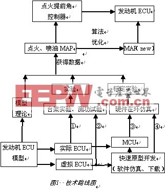
Using the experimental data of chassis dynamometer emissions conducted by dual-use fuel vehicles under transient conditions, a single objective function of engine torque, three harmful emissions and ignition advance angle (or air-fuel ratio) is established; a comprehensive objective of multi-objective optimization is established Function; optimization based on intelligent algorithm (multi-object ant colony genetic algorithm) in Matlab environment; obtain a new MAP map and write it into the engine ECU for verification.
Engine model and software simulation
The concept of engine average modeling was first proposed by Rasmussen. After the development of Powell et al., Hendricks systematically summarized and refined the model structure and general expression form. It uses the average value of variables in several engine cycles to describe the dynamic process of the engine, and the average model is also named accordingly. The most common and common mean model now consists of three subsystem models, namely the intake manifold air flow sub-model, fuel evaporation and flow sub-model and power output sub-model.
Taking a certain brand of dual-fuel four-cylinder gasoline electrical control system as the research object, Simulink was used to build an engine electronic control system model based on the average model, mainly the engine ECU comprehensive simulation model and engine calibration system model, including the intake air Module, fuel module, crankshaft module, sensor module and air-fuel ratio control, ignition advance angle control module, dynamometer module (load regulator module) and emission module. Among them, the emission module is a model based on the regression relationship between the air-fuel ratio, the ignition advance angle and the emission based on the vehicle dynamometer detection experiment of a vehicle transient operating method in a Guangdong testing station.
System principle
The structure of ECU rapid prototyping system based on PXI is shown in Figure 2 (a). The rapid prototype of ECU composed of CompactRIO is the model under test, and PXI is the test system. After downloading the ECU controller model [11] to the real-time hardware platform-CompactRIO, CompactRIO is equivalent to a virtual ECU, connected to the PXI system through the I / O port. The PXI system can simulate signals such as temperature sensors, crankshaft sensors, and throttle opening, and measure the data output by the virtual ECU.

PXI-based real ECU in-loop simulation structure is shown in Figure 2 (b). After the real ECU model passes the rapid prototyping process, the code generated by the model is downloaded to the ECU, and the generated target code is tested. The high-speed adjustable pulse output by the digital acquisition card of the PXI system is used as the input of the crankshaft pulse and the camshaft pulse of the ECU. The ECU calculates and outputs the ignition pulse width signal and the fuel injection pulse width signal to the PXI system through the optimization strategy.
Construction of system hardware environment
Hardware of ECU rapid prototyping system based on PXI
The connection diagram of this experimental system is shown in Figure 3 (a). For example, the PXI system provides the thermocouple temperature (engine water temperature, oil temperature, ambient temperature, etc.) and the AO MOD3 / AO0 speed signal for the AI ​​MOD1 / TC0 in the ECU rapid prototype.
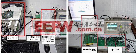
(a) ECU rapid prototyping (b) real ECU in-loop simulation
Figure 3 PXI-based ECU-in-the-loop simulation system hardware connection ECU rapid prototype is built by CompactRIO system and uses NI RIO technology, FPGA chip and LabVIEW can be used to customize the measurement hardware circuit, and reconfigurable FPGA technology can be used to automatically synthesize highly optimized Of the circuit, thereby realizing input / output, communication and control applications. Compile the ECU model of the engine into a dynamic link library file and download it to the FPGA of CompactRIO. CompactRIO is a virtual ECU.
PXI-based real ECU-in-the-loop simulation system hardware
The hardware connection of simulation experiment of real ECU based on PXI is shown in Fig. 3 (b). The high-speed adjustable pulse output by PXI 6602 is used as the crankshaft pulse and camshaft pulse input of the ECU. The ECU calculates and outputs the ignition pulse width signal and the fuel injection pulse width signal through the optimization strategy, which is collected by the PXI 6259. The waveform is displayed to determine whether the target hardware meets the requirements.
Construction of system software environment
Software Design of Rapid Prototyping System Based on PXI ECU
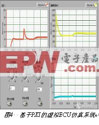
Build a simulation environment for ECU rapid prototyping, connect the output port of the PXI data acquisition card to the AI ​​port of CompactRIO, and provide simulation signals such as throttle opening value and ignition advance angle; then connect the PXI input port to the AO port, use LabVIEW The designed software interface uses control components to adjust the output voltage and observe the output waveform of CompactRIO on the display control. Figure 4 shows the software interface of the ECU rapid prototyping system based on PXI.
Throughout the implementation and experiment of rapid prototyping, the LabVIEW Real-TIme module is an additional component used in the LabVIEW development system. This software compiles and optimizes LabVIEW graphical code for specific real-time targets; with NI LabVIEW FPGA and reconfigurable I / O (RIO) hardware, you can create custom I / O and control hardware without prior knowledge of traditional HDL Language or hardware board design.
The ECU rapid prototyping process is as follows:
1) Use Matlab Simulink to generate the DLL file of the ECU model for compilation into CompactRIO.
2) Use LabVIEW to generate the lvbit file of CompactRIO, and initialize the I / O port of CompactRIO.
3) Connect LabVIEW and CompactRIO, and download the DLL of ECU model to CompactRIO.
4) Call the lvbit file of CompactRIO in the SIT manager, and set the input and output ports related to the model.
5) Use the function generator to input the AI ​​port of CompactRIO, and observe the output port of CompactRIO with an oscilloscope.
6) Use the PXI system, oscilloscope, and voltmeter to input the AI ​​port of the CompactRIO and output the AO port of the test, and record the waveform and data.
Software design of real ECU-in-the-loop simulation system based on PXI
Use the LabVIEW DAQ assistant and the simulation signal module to create an analog signal input and output program. The sampling setting is set to continuous sampling, the number of samples is 15000, and the sampling rate is 10 kHz. The voltage signal of the simulation throttle opening degree is selected to be DC output. Experiment and Analysis
Rapid Prototyping Test of ECU Based on PXI
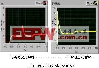
Connect the hardware according to the connection method of PXI and virtual ECU, the ignition advance angle is set to 15 °, the throttle opening is 7 °, the set speed is 4500 r / min, click RUN to start the test. The changes in torque and crankshaft speed are shown in Figure 5 (a) (b). Click Save Data to save the data in CSV format.
PXI-based real ECU in-loop testing
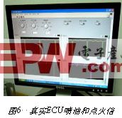
When the crankshaft speed is set to 1000 r / min, click RUN to start running. Figure 6 shows the 1-4 cylinder ignition signal, 2-3 cylinder ignition signal, 1-cylinder fuel injection and 2-cylinder fuel injection signals output by the hardware ECU.
The application of HIL simulation system reflects the following characteristics:
1) The system user interface is friendly, intuitive and easy to use, and the interface can be customized.
2) The PXI system meets the requirements of ECU development accuracy, can be repeatedly configured, and the expansion module is convenient. It is suitable for low-risk, low-cost, and short-cycle development of ECUs.
3) Test data can be accessed in CSV format to facilitate subsequent data processing.
The experimental error analysis was carried out, and the relative error of the system was <3.9%, which met the requirements of the ECU test. Finally, the rapid prototyping of ECU based on PXI and the real ECU in-loop test based on PXI were carried out.
Transient test
The PXI-based CompactRIO virtual ECU calibration system has an output signal waveform at a speed n of 5000 r.min-1, a throttle opening Throttle of 17, Pm of 43 kPa, and an ignition advance angle θ of 9 °, including crankshaft speed n, Intake pressure Pm, fuel injection quantity signal Mass Fuel, oxygen sensor O2, torque T, HC emissions, CO emissions, NOx emissions, air-fuel ratio AFR, and power PO. When the ECU model in Simulink is compiled and run on the CompactRIO virtual ECU, the PXI system provides the required input signal and test the output signal to the ECU rapid prototype. The output signal waveform and data are obtained by the LabVIEW oscilloscope module and data storage module.
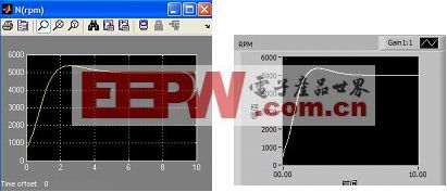
Taking the speed n as 5000 r.min-1, Pm as 43 kPa, and ignition advance angle θ as 9 ° as an example, the output waveform of the Simulink system simulation result is similar to the actual output waveform of the virtual ECU calibration system, and the error is small. Fig. 7 is a comparison diagram of parameter rotation speed, in which Fig. 7 (a) is Simulink output, and Fig. 7 (b) is virtual ECU output.
Analysis and discussion of steady-state test data
Table 1 shows the steady-state operating data of the engine with a speed of 5000 r.min-1 and an intake pressure Pm of 39 kPa (taking the parameter speed as an example). It is calibrated under 10 ignition advance angles, and then in the ring with Simulink software. Error analysis of simulation data comparison.

Under the steady-state operating conditions of engine speed 5000 r.min-1 and intake pressure Pm of 39 kPa, 43 kPa, 48 kPa and 54 kPa, respectively, the calibration at 10 ignition advance angles was performed to obtain the ignition advance angle MAP diagram, based on the simulation results of Simulink system, the relative error of each parameter averages <0.5%. Table 2 is a comprehensive analysis of the average A and the relative error average B of the sum of the absolute values ​​of the 10 parameters.

in conclusion
The research of ECU rapid model development is of great significance to the research of domestic independent brand car engines and new energy vehicles. Taking a brand dual-fuel four-cylinder gasoline electronic control system as the research object, a Simulink engine electronic control based on the average model was constructed System model, including engine ECU comprehensive simulation model and engine calibration system model.
For dual-use fuel engines, a PXI-based engine ECU hardware-in-the-loop simulation system was built using virtual instrument technology, and the relative error of the system was less than 3.9%; the virtual engine ECU was quickly built to implement the Simulink model based on CRIO and the system Error Analysis.
Auto spare lamp kits are extra lamp pieces that can be used to replace a piece that broken. There are many different bulbs and fuses in one spare lamp kits. For example, there are one H4 for headlight, one S25 singe filament for signal light, one dual filament S25 for stop light, one G18.5 for truck light or license plate light, one T10 for interior light or side indicators light and two different types of fuses that can replace the burned fuse. The customers will review what specs their own vehicle have and choose which to buy. Having a spare lamp in the car is like buy a insurance, because every light on the car has its specific purpose, which means any broken bulb might put the driver and others in a very dangerous situation. Highly recommend have one kits in the car.
Auto Spare Lamp Kits
Auto Spare Lamp Kits,Auto Bulb Halogen Parking Lamps,Car LED Auto Light,Super White Headlight
Heshan Jianhao Lighting Industrial Co., Ltd. , https://www.sunclubtw.com