Radio Frequency Identification (RFID) is one of the fastest growing wireless technologies in recent years, bringing the benefits of bar code and wireless technology to asset management, product tracking, shipping and transportation identification, inventory control and location detection. Most RFID systems use passive tags that draw power from the reader via RF. This helps reduce label size and cost, but limits read range and data storage. Active tags with batteries provide a wide range of readability and reliability, but they are larger and more expensive. Using the latest low-power single-chip microcomputer and wireless data transmission chip, designing an active RFID tag with not only long reading distance, high reliability, lower cost and longer life is the purpose of this design study.
Design analysis
The active RFID completed in this design should have the characteristics of low cost, low power consumption, long reading distance and adjustable distance, and battery power supply. Analyze these characteristics of active RFID and form a design as follows:
Low cost: In the case of a typical RFID-based electronic identification system, RFID tags used to mark objects always have a large amount of usage. The unit price of the label directly affects the overall cost of the system.
low. Although active RFID has advantages over passive RFID, such as long recognition distance, fast recognition speed, and good anti-collision performance, if the price difference is large, it will become an obstacle in application promotion. Therefore, the cost of the label should be reduced as much as possible.
Starting from the device selection, the MCU and wireless data transmission chip with high integration are selected to minimize the number of peripheral devices, which not only reduces the hardware cost, but also avoids the adjustment work in the production process and reduces the production cost. This design uses MSP430F2012 single-chip microcomputer, the internal PLL circuit can save the external crystal oscillator necessary for the general single-chip microcomputer; the built-in power supply voltage monitoring/undervoltage reset module (BOR) eliminates the external reset circuit; the IA4420 wireless data transmission chip is the same type of wireless data. The least number of peripheral components in the chip (only one 10MHz crystal oscillator is required); the differential antenna interface can be directly connected to the microstrip antenna designed on the PCB. These all make the hardware cost of this design to a minimum.
Low power consumption: Because active RFID tags are battery powered, the system has strict requirements for low power consumption in order to extend battery life. The MSP430 microcontroller has a 0.5mA hold mode standby current and 250mA/MIPS operating power. It is an industry-recognized low-power microcontroller; the IA4420's low-power standby mode consumes as little as 0.3mA. Provides a fundamental guarantee for the low power performance of this design. Low-power design, on the one hand, starts with the selection of components, on the other hand, it is necessary to design and optimize the reasonable operation timing. Under the premise of completing the label function, the circuit is in standby state most of the time.
Long distance and distance adjustable: The line of sight transmission distance of wireless signal in free space is proportional to the logarithm of the total gain of the system. Without increasing the intensity of the transmitted signal, the wireless receiver chip with high receiving sensitivity can be selected. Increase the effect of the transmission distance.
The IA4420 has a receiving sensitivity of -109dBm and a maximum output power of 8dBm RF signal. The measured distance of the outdoor open field is more than 200 meters. According to the "6dB" rule, in a wireless system, the total gain is increased or decreased by 6dB, and the transmission distance is extended or doubled. The signal output power of the IA4420 has 0, -3dBm, -6 dBm, -9 dBm, -12 dBm, -15 dBm, -18 dBm, and -21 dBm. It is adjustable in 8 steps, with 0, -6, -14, - 20 adjustable receiver LAN gain, enabling a wide range of multi-level adjustment of the label reading distance.
Battery power supply: This design uses a single CR2032 button-type lithium manganese battery, the nominal voltage of the battery is 3V, the capacity is 200mAh, and the intermittent discharge current is recommended to be 15mA. The CR2032 has an inherently ultra-low leakage of less than 1% per year and an extremely flat discharge curve (both of which are ideal for extending battery life). This design eliminates the battery-to-device voltage regulator circuit and directly supplies power to the system. It also saves the quiescent current consumption caused by the voltage regulator circuit and further extends the battery life. To prevent the battery voltage transient from decreasing due to the large current in the transmitting state, use a larger capacity capacitor in parallel with the battery.
Directly using the battery to power the microcontroller, a noteworthy problem is: the mechanical contact of the battery leads when the battery is replaced will generate power supply noise, so that the reset of the microcontroller is not complete and random operation is generated. The MSP430F2012 internally integrates zero-power Brown-out Reset (BOR) protection, which solves this problem by performing a full reset when the voltage is below the safe operating range.
Hardware circuit design
MSP430F2011
MSP430 is a series of ultra low power microcontrollers from TI.
Perfectly integrates low power, speed and on-chip peripherals: The CPU uses a 16-bit reduced instruction set and integrates 16 general-purpose registers and constant generators, greatly improving code execution efficiency; the series of microcontrollers will also have a large number of peripherals The module is integrated into the chip and is suitable for a more complete system-on-chip; five low-power modes are provided for battery-powered applications. The MSP430 series used in this design is a new low-cost, higher-performance single-chip microcomputer, MSP430F2012.
IA4420
The IA4420 is an integrated wireless data transmission chip introduced by IntegraTIon. The RF function is fully built-in and can be operated with a single 10MHz crystal.
The circuit diagram of the active RFID tag is shown in Figure 1.
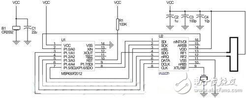
Figure 1 Active RFID tag circuit diagram
Protocol
All tags and readers' wireless data transmissions operate on the same radio frequency. In the case where there is only one tag in the reading range of the tag reader (wireless signal coverage), the tag performs point-to-point wireless communication with the reader, and the radio signal does not collide. But if the read range of the reader has multiple tags, you need to consider multiple tags at the same time.
Radio signal generated when transmitting data (multiple access)
Suddenly develop a corresponding anti-collision machine
System to solve.
This design complies with all the conventions of the physical layer and data link layer of the active RFID tag communication protocol in ISO/IEC 18000-7 "433 MHz Active RFID Air Interface Communication Parameters".
Conclusion
This design optimizes the circuit by reasonably selecting components, and optimizes the circuit around the characteristics of low cost, low power consumption, long distance, battery power, etc., and complies with the ISO/IEC standard communication protocol in design, and designs the active RFID tag in performance index and stability. It is very advantageous in terms of compatibility with international standards and low hardware costs.
The RFID tag completed with this design and the associated reader can form an electronic identification/positioning system for personnel or articles, and are widely used in many fields such as mining, industrial production, road transportation, logistics and transportation, medical treatment, medicine, national defense and safety.
Dimmable class 2 led driver is the most compact 12V/24V DC Dimmable Led Driver on the market with UL 8750 listed. The series led driver is class 2 rated and designed to operate with any standard MLV/Incandescent TRIAC (Leading edge) dimmer switch. Encased in a low profile coated metal box that includes 2 knock-outs, one on each side, to enable easy installation that complies with electrical code requirements.


Waterproof Led Driver,Led Driver Zf120A,75W Dimmable Led Driver,Led Driver Dimmer 220V
Shenzhenshi Zhenhuan Electronic Co Ltd , https://www.szzhpower.com