Gasoline generator set is a supporting equipment for a certain type of radar. Due to the strong vibration of the unit during operation, the set position of the potentiometer is easily changed, which causes the reference of the protection circuit to change, so that the unit cannot work normally.
Digital circuits and computer program control are increasingly used in modern electronic products. The advantages of digital circuits are strong anti-interference ability and stable operation, which can effectively avoid equipment performance degradation caused by component parameter changes. After using computer program control, the necessary parameters can be solidified in the program or stored in the non-volatile memory, which fundamentally solves the abnormal work caused by the change of the setting reference. Therefore, in view of the problems found in the use of a certain type of gasoline generating set, an improved design of the control and protection circuit of the unit using digital circuits and computer program control is proposed.
1 Design analysis
1.1 Functional block diagram of control and protection circuit
The block diagram of the control and protection circuit of a certain gasoline generator set is shown in Figure 1, and the PWM control sequence is shown in Figure 2.
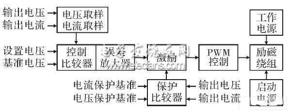
Figure 1 Block diagram of the control and protection circuit

Figure 2 PWM control timing
1.2 Control and protection process analysis
(1) Output voltage setting.
The reference voltage in Figure 2 is the clamping voltage. As shown in Figure 2, when the voltage setting potentiometer is adjusted to increase or decrease the setting voltage, the output pulse of the control comparator will become wider or narrower, the conduction time of the generator excitation winding will change accordingly, and the generator output voltage will also be The ratio rises or falls until it reaches a steady state.
(2) The output voltage is stable.
The output voltage of the generator is fed back to the control comparator after sampling by the voltage transformer. When the set voltage is fixed and there is no load change to cause the output voltage to change, the control comparator will turn on the excitation winding with the pulse control excitation tube and power tube with fixed output width. Because the conduction time of the excitation winding is fixed, the output voltage is at a stable value.
As shown in Figure 2, when the output voltage of the generator changes, because the reference voltage and the set voltage are unchanged, the control comparator will adjust the output pulse width, and finally the output voltage will be stabilized at the set value again.
(3) Output protection.
The output voltage and output current of the generator are connected to the protection comparator after sampling by the voltage transformer and the current transformer. When the generator output voltage is higher than the preset upper limit of the output voltage or lower than the preset lower limit of the output voltage, and the output current is greater than the preset upper limit of the output current, the output of the protection comparator is forced to cut off the excitation tube, and the output signal of the comparator is controlled Inactive, the excitation winding is turned on to control the power tube without an input excitation signal and is also in the off state, so that the excitation winding has no excitation current and the generator stops output.
1.3 Analysis of automatic control principle
In summary, the control and protection circuit of a certain type of gasoline generator set is a typical first-order closed-loop automatic control system. Since the output disturbance mainly caused by load change is introduced at the input of the control comparator, it is a first-order compound closed-loop automatic control system based on disturbance compensation. The block diagram of the automatic control principle of the generator control circuit is shown in Figure 3.
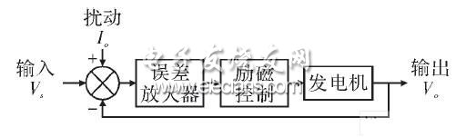
Figure 3 Block diagram of automatic control unit
In the figure, input: system input is the set voltage Vs generated by the (output adjustment) potentiometer on the control panel. Output: The system output is the generator generator output voltage Vo. Disturbance: System disturbances include changes in unit generator output current, unit engine speed changes, temperature changes, and other factors that cause unit generator output voltage changes. Among them, the generator output current, Io change is the main external disturbance signal.
2 Improve circuit design
The improved circuit design uses an A / D converter to digitally quantize the set voltage Vs, output voltage Vo, and generator load I / O; uses MCU for data processing; and E2PROM completes parameter saving. The block diagram of the improved genset control and protection circuit is shown in Figure 4.
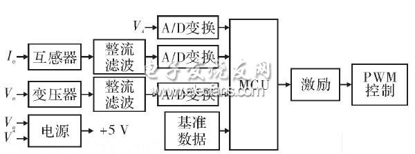
Figure 4 Block diagram of the control circuit
Since the generator set has a 50 Hz AC output, in order to increase the number of control processes, full-wave rectification must be used. At the same time, in order to balance noise filtering and signal lag, a smaller rectifying filter capacitor should be used.
3 Programming
The control and protection program is composed of A / D conversion control program module, E2PROM read / write control program module, output protection program module and PWM output control program module. After using computer program control, it is still a disturbance compensation first-order compound closed-loop automatic control system based on PWM control mode.
(1) A / D conversion control program module.
This design uses a serial output A / D converter. The timer interrupt is provided by the internal timer of the MCU, and the A / D conversion control program module is called to complete the digital quantization of Vs, Vo, and Io.
(2) E2PROM read / write control program module and output protection program module.
The E2PROM read / write control program module reads the preset data and compares it with the A / D quantized data. When the comparison result meets the protection conditions, the output protection program module is called to complete the output protection control.
(3) PWM output control program module.
The PWM output control program module completes the PWM time adjustment control, and the control relationship is: T = K1Vs + K2Io + K3 â–³ V. In the type, T is the excitation winding conduction time; Vs is the set voltage; Io is the output current value; â–³ V is the output voltage Vo change value; K1, K2, K3 are gain control coefficients.
The A / D quantized data of Vs is smoothed and multiplied by K1 to obtain the basic output time.
In order to improve the control response to the change of the output current Io, the A / D quantized data of Io is smoothed and multiplied by K2 and added directly to the basic time as additional adjustment time. deal with.
The processing of â–³ V is the key link to ensure the control response performance. â–³ V is the algebraic difference between the current Vo sampling data and the previous Vo sampling data. â–³ V data is multiplied by K3 after smoothing and filtering, and it is used as additional adjustment time and basic time to perform algebraic operation to obtain the final PWM control time.
The dynamic characteristics of the system mainly depend on the gain control coefficients K1, K2, K3. When the gain control coefficient is small, the system response speed is slow, and when the gain control coefficient is increased, the system response speed is significantly improved.
The system control accuracy depends on the dynamic range of the A / D converter. The dynamic range of the A / D converter is increased, the system control accuracy is improved, and the system dynamic characteristics will also be improved. Because the 8-bit MCU device is used in this design, the program calculation complexity and program running time also increase after the dynamic range of the A / D converter increases. Therefore, comprehensive consideration is needed to determine the dynamic range of the A / D converter.
4 Test results
The electrical schematic diagram, printed circuit board and control program were designed according to the improvement plan, and the generator set control test was carried out. The test results and indicators are shown in Table 1.
Table 1 List of test results of main inspection items
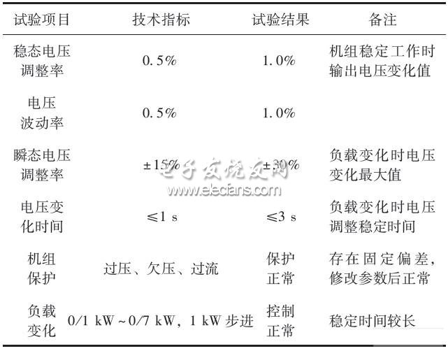
When testing the steady-state voltage regulation rate and voltage fluctuation rate, it was found that adjusting the minimum PWM adjustment value only caused a change in the adjustment time and could not improve the voltage adjustment rate index. The analysis determined that the resolution of the A / D converter was insufficient.
When testing the transient voltage adjustment rate and voltage change time, it was found that adjusting the PWM maximum adjustment value can significantly improve the dynamic control characteristics, but at the same time cause the steady-state characteristics to deteriorate. The analysis determined that in addition to the insufficient resolution of the A / D converter, the various coefficients in the system control relationship should also be combined and optimized.
5 Conclusion
The digital improvement design scheme for the control and protection circuit of the gasoline generator set described in this paper has achieved initial results. The newly designed control board realizes the unit control and protection functions, and is further optimizing the design to fully meet the requirements of technical indicators. The optimal design measures are as follows:
(1) Increase the dynamic range of the A / D converter and improve the steady-state voltage regulation rate and voltage fluctuation rate indicators.
(2) Optimize the voltage stabilization control program and increase the response speed of voltage change adjustment.
The control and protection circuits of the small and medium-sized power generating units designed and fixed in the early stage are mostly implemented by analog circuits.
Fiber Fast Connector is used for field assembled Optical Fiber Connector ,widely used in fiber to the home (FTTH) access optical networks,to assemble with drop cable quickly. Options are available for 900 micron allowing the installer to terminate and make connection in minutes at equipment and fiber patch panels.This connector system removes any requirement for epoxy,adhesive or costly curing ovens and polishing and fiber interface inspection. It's more convenient and faster
Fast Connector
Optical Fiber Connector,Fiber Optic Connectors,Fiber Optic Cable Connectors,Optical Fast Connector
Chengdu Xinruixin Optical Communication Technology Co.,Ltd , https://www.xrxoptic.com