The Design and Application of Image Processing Technology in Parts Surface Damage Detection
The problem of surface damage detection
Accurate and rapid detection of surface defects on parts is directly related to product quality. If unqualified products are not removed in time, there will be hidden quality problems. However, in the automobile, motorcycle, internal combustion engine and other industries characterized by mass production, the identification and detection of surface defects of key parts of important parts has so far been mainly manual visual inspection. Due to the consideration of the complexity in the process of execution (especially after the use of advanced splitting head connecting rod ups and downs process), it must also propose a standardized evaluation standard. For example, the possible damage to the joint surface of the connecting rod size head is as follows: the area of ​​the break is less than 3mm2; the linear length of the break in any direction is less than 2.5mm. As long as one of the conditions is met, it will be rejected as rejected.
According to the characteristics of the part, the area where the break may occur is outside the joint surface (line), and its range is "eight". In this case, relying on manual visual inspection and estimation is not only inefficient, but also labor intensive, and it is impossible to accurately implement the provisions of the above standards. On the other hand, even if other conventional measurement methods are adopted, it is difficult to achieve the above purpose.
The principle of image processing technology for surface defect detection
Image processing technology, also known as "machine vision", is to use the image of the measured object as a carrier of information, and extract useful information from it to achieve the purpose of measurement. It has the advantages of non-contact, high speed, large measuring range, and rich information. Through the combination of CCD (Charge Coupled Device) camera, optical system and processing system, different detection requirements can be achieved. For the identification of the above-mentioned surface defects of the workpiece, the reflection method shown in FIG. 1 can be adopted.
As shown in the figure, this system illuminates the broken area to be detected by a square LED diffuse reflection light source. After the light irradiates the surface of the object, it is reflected on the photoelectric coupling CCD component in the camera and converted into a corresponding power signal. The CCD component can be understood as a dot matrix composed of photosensitive pixels. Each pixel of the CCD corresponds to the two-dimensional image characteristics of the measured object, that is, the analysis of the "pixel imaging results" can indirectly analyze the object's The image features, for example, by calculating the number of imaging pixels in the binarized image, the length and area values ​​of the corresponding object can be obtained. The image processing system binarizes the obtained image according to the power signal, and then takes the binary image as the object for further calculation and analysis.
In actual use of the image processing system, the method of comparing the grayscale binarization threshold and the setting of the light source is implemented. The specific method of comparison: use a known sample as the reference object for calibration (comparison), and divide the measured value of the known reference object by the corresponding pixel value of the reference object to obtain the correspondence between the pixel and the actual value Scale value. By adjusting the brightness of the light source and the binary threshold of the system, the binary threshold of grayscale is optimized to ensure that the system has a relatively high resolution for the object boundary, that is, the optimized binary threshold and the light source can make the boundary The change produces as large a change in pixel value as possible.
As a novel and practical sensor technology, the image detection unit has been commercialized in recent years. Some well-known manufacturers, such as Panasonic Corporation of Japan and Siemens Corporation of Germany, have launched a series of products with complete specifications, including light sources. , Camera, image processor, etc., which create very favorable conditions for the popularization and application of image detection technology. At the same time, the relevant enterprise standards promulgated not only regulate the production, but also provide the basis for users to select the appropriate detection unit in different situations and carry out system design faster and better.
According to the characteristics of the measured object (workpiece, measured part), referring to the relevant standards, it will be easy to select the appropriate image detection unit. Taking the connecting rod as an example, since the fracture defect area of ​​the joint surface cannot be greater than 15 × 15 m m2, it is more appropriate to select the field of view of 20 × 21.4 m m2 from the corresponding standard. With respect to each field of view and depth of field, users can choose cameras with different focal lengths, such as 8, 16, 25, and 50 models. Each focal length corresponds to the characterization of the distance from the lens to the measured surface al and the characterization of the lens to CCD photosensitive surface distance ba and other two parameters. According to the situation of the workpiece to be measured, choose a camera with a focal length of f = 25mm. At this time, the above two parameters are 137mm and 9mm, respectively. In this example, the Panasonic company's small image detection unit is used. The core component of the CCD photosensitive film has 512 × 480 pixels. In the case of a fixed field of view, the measurement resolution of the selected detection unit can be obtained accordingly:
X resolution:
21.4 / 512 = 0.0417mm
Y resolution:
20.0 / 480 = 0.0417mm
Area resolution:
0.0417 × 0.0417 = 0.00174mm2
In the reflection-type image measurement shown in Fig. 1, the light source has two forms of combination in the camera and split arrangement, and the light source itself has a variety of fluorescent lamps, halogen lamps, lasers and LED light sources. According to the specific situation of this example, the LED light source scheme of split arrangement is adopted, and this type is easy to adjust.

Figure 1 Principle of reflection image measurement
The composition, design features and operation process of special testing equipment
The composition of the system
The formation of the measurement system program is based on the characteristics of the object to be measured. On the one hand, as described above, the distribution range of the fracture defect on the joint surface is in the shape of an "eight", which indicates that in order to complete an inspection, it is necessary to measure in three directions; On the other hand, the process and production departments have also put forward requirements for full inspection. Therefore, it was decided to adopt a semi-automatic scheme, that is, except for the manual loading and unloading of the workpiece, the entire measurement process is automatic to adapt to the faster working rhythm.
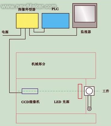
Figure 2a

Figure 2b
Figure 2a, the measurement system is mainly composed of a camera, LED light source, image processing unit, programmable controller (PLC), display and mechanical parts, etc., where the camera is used to take the image; LED light source provides a stable and long-lasting light source, Ensure the quality of image acquisition; the programmable controller (PLC) controls the function execution of the measurement system; the image processing unit processes and analyzes the data and provides signal output; the display shows the image acquisition situation and data analysis results; the mechanical part supports and Implement actions during the measurement process.
Operating process and characteristics of the measurement system
The detection device is a bench-top instrument with a very compact structure. It can be seen from the two schematic diagrams in FIG. 3 that the camera 3 is fixed at one end of the swing arm 4 and the other end is supported on the bracket 7 by a pivot. The stepper motor 5 installed on the side of the frame 9 can drive the swing arm 4 to rotate with the help of the synchronous toothed belt 6 and the synchronization wheel on the pivot shaft, and the rotation range is ± 150. The proximity sensor 8 assists positioning. Another pair of photoelectric sensors are placed on both sides of the entrance of the work piece 1 to ensure the accurate positioning of the work piece on the jig before performing the measurement and to turn on the light source.

Figure 3 Schematic diagram of special testing equipment
An example of measurement of the breakage of the connecting surface of the connecting rod
The camera, that is, the original state of the swing arm is in the rightward position (A in Figure 2b). Driven by the swing arm drive mechanism, the camera samples from the right, middle and left angles of 150 at each other, namely at ABC. At the same time, the image processing unit in the block diagram of Figure 2a uses the RS232 interface to transfer the numerical results of the camera's three consecutive samplings at each position to the programmable controller PLC for comparison. If the above three consecutive measurement results are the same, this value is confirmed as a reliable value, and then stored in the PLC stack for the final comparison of the three azimuth detection results, and find the maximum value.
If the camera's detection results are different for three consecutive times at each position, you need to perform another three consecutive samplings and compare the results. If no reliable value can be obtained after repeating five cycles (15 samplings), the entire detection system will automatically reset, and the swing arm drive mechanism with the camera mounted on it will return to the initial position on the right. At the same time, the device sends out a "system failure" signal.
As a kind of surface defect measurement, the above detection system has the characteristics of combining the visual display of images with the analysis and judgment of measurement results. For the detection of the broken area of ​​the connecting surface of the connecting rod, the image of the broken area is isolated by the optimization algorithm in the image processing. The image of the broken area is binarized into black, and the image of the other parts is white. Then, through the statistical calculation and unit conversion of black pixels, the area size of the broken defect can be obtained, and then the judgment of whether it is qualified or not can be made. As for the detection of the maximum linear length of the breach, the boundary scan method is used to find the boundary of the breach by scanning along the X direction and the Y direction, and then according to the rectangle formed by the two parallel lines, that is, the envelope The calculation of the diagonal of the rectangle at the boundary of the breach to determine the maximum linear length of the defect at the breach.
Each time the test is completed, the measurement results to be displayed on the display include: area CA01, X direction length CA02, Y direction length CA03, and maximum linear length CA04. Then, according to the pre-set evaluation index, make a judgment on the state of the joint defect. In order to facilitate the use of operators under mass production conditions, the upper part of the front of the machine body has a green (qualified) indicator or a red (unqualified) indicator to indicate the status of the inspected workpiece in a simpler way.
| About Glass Fiber Covered Flat Copper Wire |
Fiber Glass Covered Aluminum/Copper Wire is according to customers` requirement, aluminum/Copper conductor is evenly covered with one or two layers of non-alkali fiberglass, then it`s impregnated in compatible insulating coating of required thermal class baked to make a whole between fiberglass and aluminum/Copper conductor
Excellent resistance to abrasion and solvent, excellent electricity

a) Excellent resistance to abrasion and solvent,
b) Excellent electricity performance
c) Excellent heat shock, adherence and flexibility,
d) High cut through
e) Resistance to high voltage in oil;
f) Rise up the filling coefficient of the transformer;
g) Reduce volume and the cost of the transformer
Glass Fiber Covered Flat Copper Wire
Glass Covered Winding Wire,Glass Fiber Covered Flat Copper Wire,Fiber Glass Covered Copper Wire,Generator Flat Glass Fiber Covered
HENAN HUAYANG ELECTRICAL TECHNOLOGY GROUP CO.,LTD , https://www.huaonwire.com