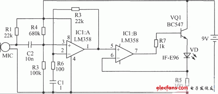
This circuit can transmit voice through 1mm plastic optical cable. On the transmitter circuit board (KIT26 T) there is a microphone and modulation LED lighting circuit. The LED is installed in a plastic case to facilitate the connection of the FO optical cable for transmission. On the receiver (KIT26 R) board there is a photoelectric receiver, a speaker and a circuit for converting the detected optical signal into an electrical signal, amplifying and converting it into sound waves. Voice signals are transmitted in optical cables in the form of light waves and are not affected by any electric or magnetic fields. Long transmission distance and strong anti-interference ability. Each circuit board requires a 9V battery, but it is recommended to use a rectified power supply for continuous use. The device is equipped with a 4.3m plastic optical cable with a diameter of 1mm. This line can well transmit signals through 183m optical cable. Note: The plastic optical cable used here is not a 1μm glass optical cable, and the use of glass optical cable can communicate at a farther distance (about 32km). The experimental application of plastic optical cable is very convenient, and the short-distance communication in the electronic noise environment has obvious anti-interference effect. This circuit is assembled on a single-sided printed circuit board.
How it works: The audio signal is initially a sound wave, which is converted into an electrical signal by the transmitter's electronic microphone. This signal is amplified by an audio amplifier composed of LM358, and the terminal voltage of the LED is controlled by a separate transistor to convert the electrical signal into an optical signal. The optical signal is fed into the plastic optical cable. At the other end of the fiber optic cable, the optical signal illuminates the photocell of the receiver. The photocell then converts it into an electrical signal. This signal is amplified and sent to the speaker to be converted into sound waves.
Transmitter component selection: IC1 selects LM358 integrated circuit. VQ1 selects BC547 transistor. C1 selects 0.1μF monomer capacitor. VD selects IF-E96 photoelectric transmitter (pink dot on blue background). Other components are shown in the figure.
Receiver component selection: VT selects IF-D93 photoelectric detector (red dot on black background). C2, C3, CA, C6 all use 0.1μF single capacitor. Other components are shown in the figure.
Transmitter circuit board:

Photoelectric receiver:

European Series Extension Sockets
Wall Electrical Outlet,Multi Plug Wall Socket,England Outlet Adapter,Wall Mounted Multi Socket
Heikki Technology Co., Ltd. , https://www.heikkipower.com