In recent years, radio frequency identification (RFID) technology is a technology that uses wireless electromagnetic wave signals to exchange energy and information with tags through near-field or far-field methods to achieve identification purposes. It has large data capacity, no need to touch and read, high confidentiality, and longevity. Long, strong anti-interference ability. Applications in industrial automation, commercial automation, transportation control management, and logistics management are becoming more widespread. According to the working frequency band, RFID systems can be classified into low frequency, high frequency, ultra high frequency and microwave. At present, most RFID systems are low-frequency and high-frequency systems, but the RFID system in the ultra-high frequency band has the advantages of long operating distance, fast communication speed, low cost, small size, etc., and is more suitable for future logistics and supply chain applications. The realization of the Internet of Things offers the possibility.
This paper introduces a new UHF band RFID reader design. The reader is based on Intel R2000 chip, with AT91SAM7S256 as the microcontroller, in line with ISO 18000-6C and EPC global Gen2 standards. Compared with traditional UHF RFID systems, this solution simplifies the design process, reduces the size of the reader, reduces production costs, and shortens the product production cycle.
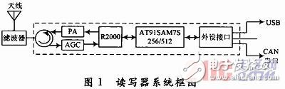
1 reader system block diagram
The R2000-based reader system structure is shown in Figure 1. The controller uses the ARM7 core processor. In addition to some necessary peripheral components of the R2000, a circulator must be added between the system and the antenna to meet the single antenna application. The TX port must also Add power amplifier module. According to the system block diagram of the reader, the main device selection is as follows:
1.1 RFID Broadband Circulator HYG504XX
As a transceiver for single-antenna applications, the circulator is typically made of a ferrimagnetic composite material. The material is anisotropic. The circulator is a three-port device. Port 1 is the input, port 2 is the output, and port 3 is the port. Isolating the port, the energy can hardly pass through, and so on. Generally, the UHF reader uses a circulator to make the signal flow clockwise. When the port 1 is the TX output, the RF signal will flow through the port 2, and the port 3 That is, the RX port is an isolated terminal. The specific isolation needs to refer to the device parameters and the LAYOUT effect. Conversely, when the port 2 receives the signal as the transceiver multiplexing terminal, the signal enters the port 3 in a clockwise direction, and the energy leaked to the TX port at this time. Very small, can be ignored, and the energy leaked by the TX to the RX port largely affects the receiver sensitivity, that is, the actual recognition effect. Therefore, according to the LNA parameter of the receiving end, the TX leakage signal is effectively isolated at the RX end plus the attenuator. However, this causes a problem, because the useful signal received by RX is very small, and the RX-end useful signal is further weakened while the TX-side leakage signal is attenuated. It will also affect the reception of the LNA. Therefore, the use of the circulator for transceiver isolation can only produce effects to a certain extent. For the case where the TX output power is given and the ERP does not exceed the relevant regulations, the receiver sensitivity must be considered. Increase the isolation of the two channels, depending on the specific needs.
1.2 RF Switch HMC174
Used to control the on/off of the RF output. In the 900 MHz band, the input 1 dB compression point can reach 39 dBm, which fully guarantees that the HMC174 can withstand high input RF power. The input 3rd order intercept point can reach 60 dBm, while the output power of the previous stage frequency synthesizer is within 3 dBm, thus ensuring the high linearity of the signal after passing the RF switch, minimizing the distortion of the RF signal.
1.3 RF Power Amplifier PF01411B
The PF01411B is used to amplify the TX terminal output signal of the R2000 to meet the maximum power output requirements. The main features of the PF01411B are: high gain: three-stage amplification, input power 0 dBm; high efficiency: output power up to 45% at 35.5 dBm; wide gain control range: typical value up to 70 dB.
1.4 RF numerical control attenuator HMC273
The HMC273 is used to attenuate the R2000's TX output signal for power correction.
1.5 Impinj Indy R2000 UHF RFID Reader Chip
R2000 is a new generation of UHF band RFID reader SoC chip, in line with EPC global UHF Class 1 Gen 2/ISO 18000-6C international standard, integrated ASK modem, filter, power amplifier, FPGA and other modules.
1.6 Micro Processing Unit AT91SAM7S256
The device is a 32-bit microcontroller that greatly enhances the real-time performance of the microcontroller and integrates a full suite of safe operating functions, including monitors, power supplies, and flash memory hardware protection from the on-chip RC oscillator. In addition, the device can access a single clock cycle at 30 MHz under worst-case conditions.
2 power modules and peripherals
The power module provides 5 V, 3.3 V, and 1.8 V, and the peripherals are on the same backplane. The 12 V DC voltage output from the adapter is converted to 5 V by the monolithic switching power supply LM2676. As shown in Figure 2, other required voltage values ​​are generated by the LM1117 series LDO, as shown in Figure 3. The peripherals only provide Ethernet port, USB port, and serial port.
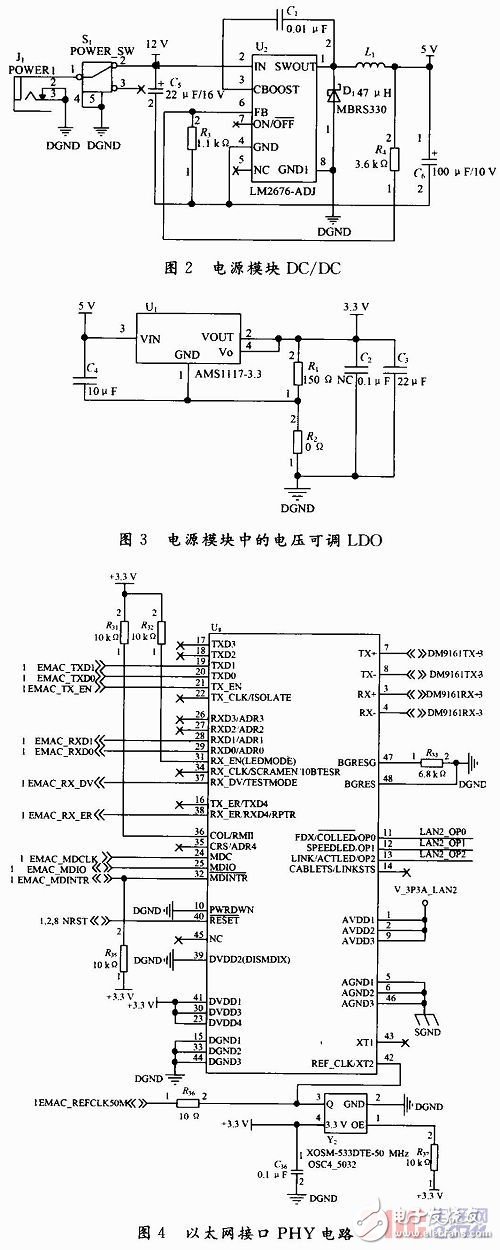
AT91SAM7S256 comes with Ethernet MAC, just choose a PHY, here choose DM9161AEP, the circuit is shown in Figure 4.
The PHY and MAC interfaces use the RMII interface, and the Ethernet interface uses the HR911105A with integrated network transformer to increase the reliability of signal transmission. USB interface circuit shown in Figure 5, because the AT91SAM7S256 chip comes with a USB controller, this part of the circuit is relatively simple, just follow the ATMEL reference circuit design. The serial port circuit is shown in Figure 6. One of them is used for debugging. In the case of no display device, the startup information can be printed out from this serial port to the HyperTerminal in Windows, which is convenient for designing the previous debugging process.
3 system software design main program
The reader works under the supervision of the host, and the system forms a master-slave communication mode with the host. After the main control module is powered on and completes the normal initialization process, it enters the waiting state, and waits for the host to send an instruction. After receiving the host command, it performs the corresponding work according to the main control program. After processing, send the resulting information to the host. The main program flow is shown in Figure 7.
4 Conclusion
This article uses Impinj's latest R2000 for UHF RFID design, which supports multi-protocol compatibility and tag processing speeds of up to 400 per second. This UHF RFID system is especially suitable for logistics and supply chain. Experiments show that the core reader has good anti-collision performance and the advanced DRM algorithm supports 400 tags per second. These features reduce the development complexity of the device, shorten the development cycle of the device, improve system performance, and speed up the time to market.
51V Battery Pack,Portable Battery Box,Portable Battery Bank,Ac Battery Pack
Zhejiang Casnovo Materials Co., Ltd. , https://www.casnovonewenergy.com