This paper briefly describes the role and working principle of the GSM base station coverage extension system.
The emphasis is on the analysis of the system uplink and downlink balance after installing the base station coverage extension system and points out the relevant precautions.
I. IntroductionWith the increase of mobile users, mobile users have a wider range of activities, and mobile networks must continue to deepen the scope and depth of coverage. However, when solving the problem of mountainous roads and villages in remote areas, traditional network optimization methods such as new base stations and repeaters are difficult to implement in engineering, and the investment cost and benefit return are not reasonable.
It is well known that the coverage of a base station to a terminal can be expanded by enhancing the transmission power of a base station. Through the free space attenuation formula: Ls=32.45+20*log(f)MHz+20log(d)Km, it can be known that the base station transmit power is increased by 6dBm and the coverage distance is doubled. The receiving signal of the mobile phone is strengthened, but the maximum power of the ordinary mobile phone is 33dBm. If it is far away from the base station, the uplink signal of the mobile phone cannot be parsed if it is not enhanced. As a result, the system has unbalanced coverage on the upstream and downstream, and the consequences are single-pass, poor quality, and dropped calls. The base station coverage extension system improves the coverage of the base station from both the base station system and the downlink direction, and is a good solution for signal coverage and depth coverage.
Second, the base station coverage extension systemThe base station coverage extension system is mainly composed of a base station amplifier and a tower amplifier, which are referred to as a base and a tower. The base is installed in the base station room to increase the base station transmit power and expand the downlink signal coverage. The tower is a low-noise amplification device installed at the antenna port of the base station to enhance the uplink transmission power of the mobile phone and improve the receiving sensitivity of the base station. The working principle of the base station coverage extension system is shown in Figure 1.
Usually, the base station carrier frequency transmission power is 43 dBm/single carrier. The 200W base amplifier output power can reach 53dBm/single carrier, and the downlink signal is enhanced by 10dB. The base station coverage extension system enhances the uplink signal by about 10 dB. The entire system can effectively extend the coverage of the base station.
Third, the impact of the installation of the base station coverage extension on the system's uplink and downlink coverage1. Analysis of the noise figure of the system by installing the tower:
The noise figure NF is used to describe the degree of deterioration of the signal-to-noise ratio of the amplifier. The smaller the noise figure, the smaller the deterioration of the signal-to-noise ratio of the output.
For a multistage amplification system, its system noise figure is:
NF=F1+(F2-1)/G1+(F3-1)/G1*G2+......
Where: F1, F2, F3... are the noise coefficients of the first to third stages, and the noise figure of the passive device is equal to the loss value.
G1, G2... is the gain from the first stage to the second stage, and the passive device gain is equal to its loss is worth reciprocal.
It can be seen from the above formula that the noise figure of the multi-stage amplification system mainly depends on the noise figure F1 of the first stage.
The principle of the tower is to improve the receiving performance of the base station by adding a low noise amplifier to the front end of the base station receiving system, that is, immediately adjacent to the receiving antenna.
2. Analysis of the balance between the upper and the lower
2.1 Definition of upper and lower balance
In the coverage area we require, the uplink and downlink links are guaranteed to be transmitted normally, and the signals received by the base station and the mobile phone can be demodulated to ensure the normal establishment of the two-way communication.
2.2 Theoretical calculation of the uplink and downlink balance of the original base station system
as the picture shows:
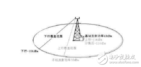
In theory, the uplink receiving sensitivity of the base station port is MBTS=-110dBm, the uplink diversity receiving gain is about F=4dB, the receiving sensitivity of the mobile phone is MMS=-104dBm, and the maximum transmitting power of the mobile phone is PMS=33dBm, assuming that the signal attenuation of the BTS to the antenna port is R. =4dB, the antenna gain is S, and the base station transmit power is T.
If upper and lower balance are required, the maximum allowable space loss HRX = the maximum allowable space loss HTX of the downlink.
Of which: MBTS=PMS-HRX+F+S-R
MMS=T-R+S-HTX
So: HRX=PMS-MBTS+F+S-R
HTX=T-R+S-MMS
Available by HRX=HTX:
In order to ensure the ideal balance between uplink and downlink, the effective power of the base station is
T=PMS-MBTS+F+MMS
=33dBm-(-110dBm)+4dB+(-104dBm)=43dBm
It can be seen that when the single-carrier transmit power of the base station is (20W) 43dBm, the uplink coverage and the downlink coverage are equivalent, and the system is in an ideal equilibrium state.
2.3. Add the upper and lower balance calculations after the base is installed.
2.3.1 Selection of tower gain.
The original base station system noise figure Nfsys (antenna port) without the tower is approximately:
Nfsys=Nfbts+Lc [Formula-1]
Where: Nfbts is the noise figure of the base station itself
Lc is the loss of the feeder loop
The noise figure of the system after installing the tower is about:
NF=NFTA+(Nfsys-1)/GTA [Formula-2]
From the above two formulas, the following conclusions can be drawn:
(1) The noise figure Nfsys of the base station before use of the tower is determined by the noise figure Nfbts of the BTS equipment itself and the antenna feeder loss Lc.
(2) The base station receiving noise figure NF after using the tower is mainly determined by the noise figure NFTA of the tower. When the feeder is long and the loss Lc is larger, the receiving sensitivity of the installed tower to the base station system is more obvious.
(3) The larger the tower gain GTA, the smaller the base station receiving system noise NF. However, if the tower gain GTA is increased, the white noise KTB level will also be increased, which will affect the base station's reception of the signal.
The bottom noise definition of a general GSM base station for a 0-level signal call quality is less than -113 dBm. Under normal temperature conditions, the white noise of the GSM system is NKTB=-121dBm. To ensure the quality of the uplink call, the receiving noise level should meet the following requirements: tower gain GTA+(-121dBm)+NF-Lc≤-113dBm. The system noise figure NF is approximately equal to 2 dB after the tower is placed. In general, Lc ≤ 4dB, so the tower gain G ≤ 10dB. Of course, the working gain of each station tower should be adjusted according to the loss Lc of the feeder circuit.
2.3.2 Selection of base power.
Under normal circumstances, when the transmit power of the base station port is 43dBm/single carrier, and the downlink coverage is -104dBm, the mobile phone signal arrives at the base station and can be demodulated, which is an ideal balance state.
Here we still first assume the following conditions:
The uplink receiving sensitivity of the base station port is -110dBm (the diversity processing gain is 4dB);
The maximum transmit power of the mobile phone is 33dBm.
The base station receives the signal with the lowest carrier-to-noise ratio C/I=9;
The noise figure of the base station itself is Nfbts=3.5dB;
The minimum carrier-to-noise ratio of the uplink signal demodulated by the base station is C/I=9-Nfbts=9-3.5=5.5 dB,
The tower noise figure is NFTA=1.5dB;
The loss of the feeder loop Lc=4dB;
Tower release gain GTA=10dB;
Dongguan Yuantong Technology Co., Ltd. is a professional production of each block cutting machine, flat mouth machine, folding machine, express bag machine, Pearl Cotton Bag Cutting Machine, slicing machine, degradation bag cutting machine, all kinds of plastic bag mold, punching machine, electrosick machine and other supporting equipment, and according to the special requirements of customers design and production of special equipment.
Express bag making machine, bag making machine,Express bag all-in-one machine
Dongguan Yuantong Technology Co., Ltd. , https://www.ytbagmachine.com